Installation of omnibearing wind collecting cap
An omni-directional, wind-wheel technology, applied in the field of omni-directional wind-collecting hood devices, can solve problems such as difficulty in collecting wind energy
- Summary
- Abstract
- Description
- Claims
- Application Information
AI Technical Summary
Problems solved by technology
Method used
Image

Examples
Embodiment 1
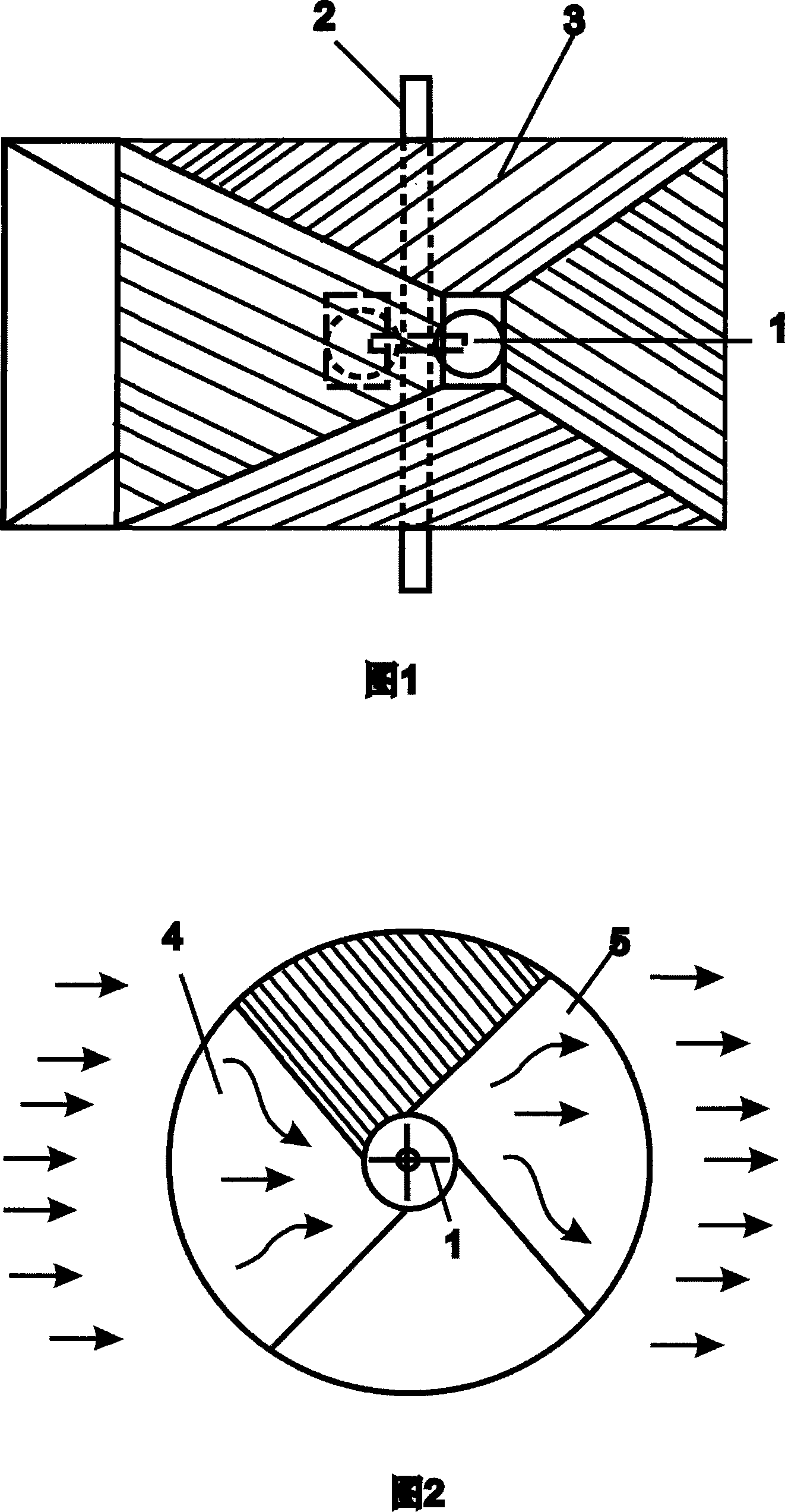
[0009] Embodiment 1: Single all-round wind collecting hood
[0010] A single all-round wind collecting hood is shown in Figure 1 and Figure 2, Figure 1 is a front view, and Figure 2 is a top view. In Figure 1, the shaded part is the front of the bell mouth 3, and the entrance is facing the hemispherical wind wheel 1. This direction of force always makes the wind wheel rotate in the same direction; the bell mouth facing the wind is the air inlet 4, and the opposite The bell mouth facing away from the wind is the air outlet 5, as shown in Figure 2, the central axis 2 is connected with the variable speed transmission machine 6 placed on the base 7. Its feature is that the wind blowing from any direction can be introduced through the bell mouth, and after being enriched, it will drive the wind wheel to rotate, and then flow out from the opposite bell mouth. In this way, no matter how the wind direction changes, the wind turbine can operate normally without changing its position. ...
Embodiment 2
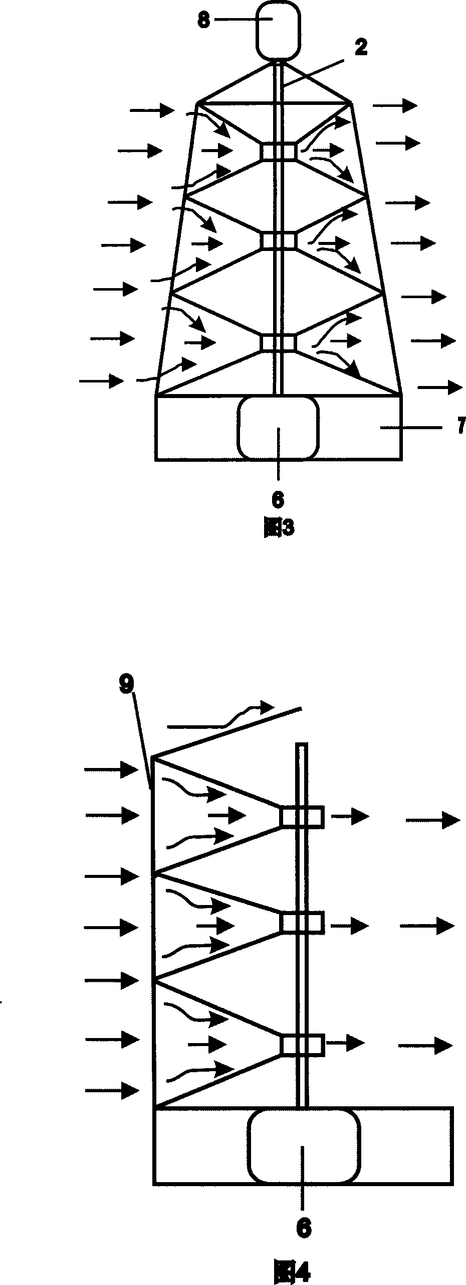
[0013] Embodiment 2: Tower-shaped wind collecting hood
[0014] Multiple wind collection hoods are superimposed on the central axis to form a tower structure, which can increase the upper and lower wind collection areas.
[0015] Compared with the current horizontal axis large paddle structure, this tower structure has high running stability. Installing the tower-shaped wind generator on the top of a mountain or a high-rise building can effectively utilize wind power. It is also possible to increase the number of layers or increase the diameter of the wind collecting hood to increase the power of the wind motor.
[0016] The tower structure can be used as a forest fire observation station on the top of a high mountain. Beacon lamp 8 is placed on the top, which can be used for high-rise aviation beacon indication.
Embodiment 3
[0017] Embodiment 3: Wind wall-shaped wind collecting hood
[0018] The all-round wind collecting hood is refitted, and only one trumpet-shaped wind collecting cover is superimposed on the central axis to form a wind wall 9, which can be called a wind wall shaped wind collecting cover, as shown in Figure 4. This single bell-mouth wind collecting hood can be combined with upper, lower, left and right planes to form a wind wall, so as to effectively utilize the wind force.
[0019] There are many places called Dafeng Pass in the mountainous area, where the wind direction changes less and is relatively simple, and the hillside ground itself plays the role of guiding and enriching the wind. A wind motor is connected through the same shaft from top to bottom, and the left and right wind motors are connected in parallel to output wind power.
PUM
 Abstract
Description
Claims
Application Information
 - R&D
- Intellectual Property
- Life Sciences
- Materials
- Tech Scout
- Unparalleled Data Quality
- Higher Quality Content
- 60% Fewer Hallucinations
Browse by: Latest US Patents, China's latest patents, Technical Efficacy Thesaurus, Application Domain, Technology Topic, Popular Technical Reports.
© 2025 PatSnap. All rights reserved.Legal|Privacy policy|Modern Slavery Act Transparency Statement|Sitemap|About US| Contact US: help@patsnap.com