

Clip-press type pipefitting
A compression-type pipe fitting and clamping sleeve technology, applied in the direction of pipe/pipe joint/pipe fitting, pipe connection arrangement, mechanical equipment, etc., can solve the problems of limited knurling depth, scratches on the inner layer of the pipe, and high installation requirements. It can achieve the effect of anti-loosening and anti-leakage, good prevention of metal electrical corrosion, and good connection effect.
- Summary
- Abstract
- Description
- Claims
- Application Information
AI Technical Summary
Problems solved by technology
Method used
Image

Examples
Embodiment Construction
[0023] The present invention will be further described below in conjunction with the accompanying drawings.
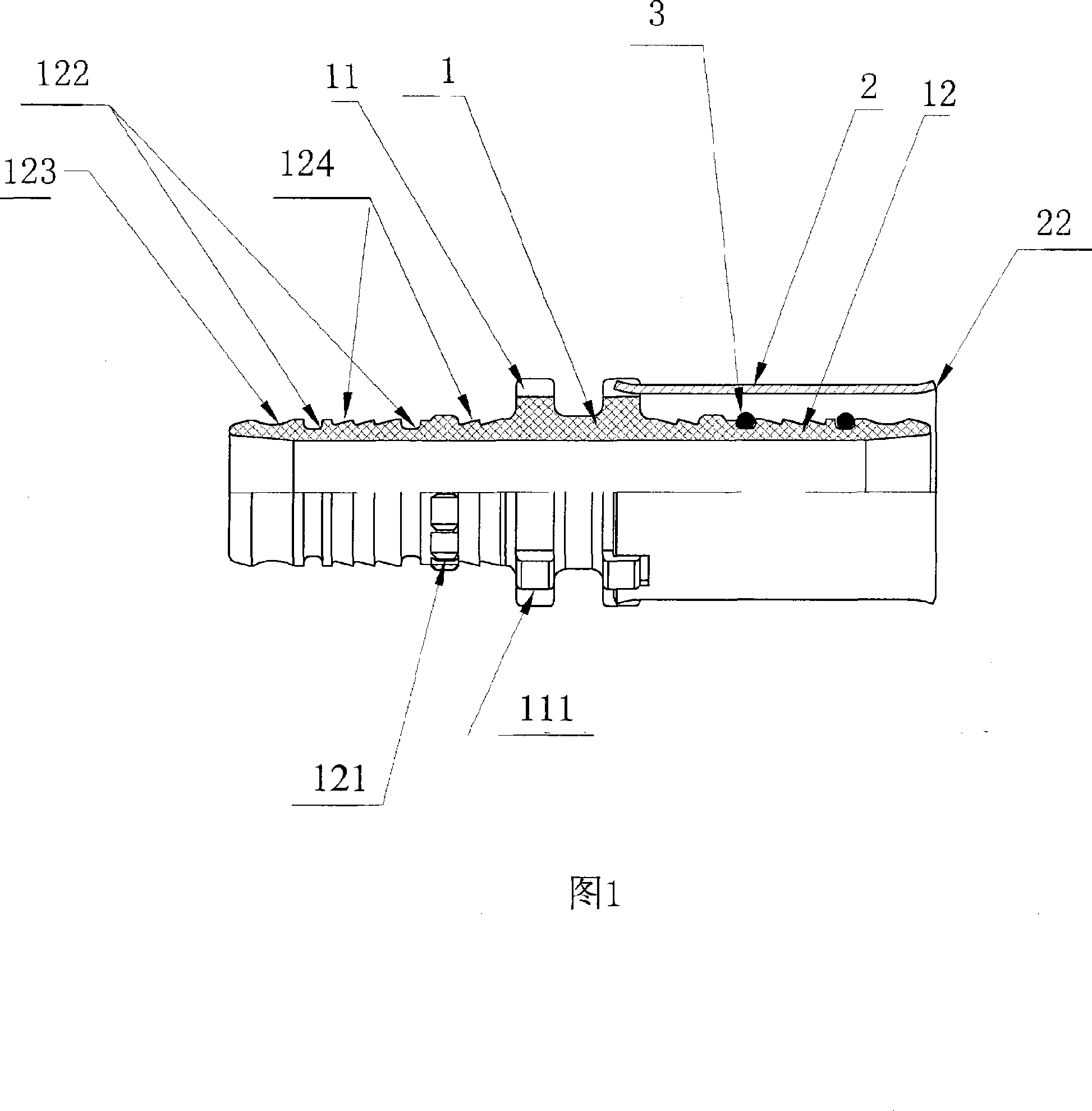
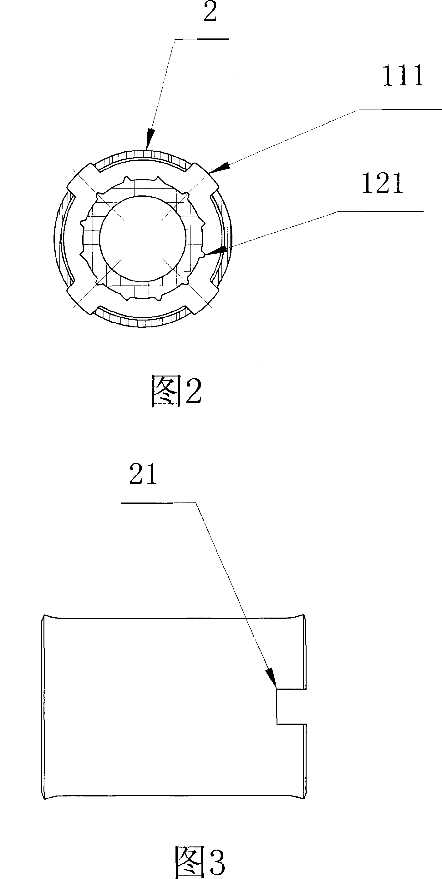
[0024] The structure diagram of the present invention is shown in accompanying drawing 1, accompanying drawing 2.
[0025] The pipe fittings include a joint body 1, a stainless steel clamping sleeve 2, and an elastic sealing ring 3.
[0026] The joint body 1 includes a body end 11 and a body core 12 .
[0027] The joint mouth of the main body core 12 is provided with a wave arc ring groove 123 to avoid scratching the inner wall of the pipe when the pipe is connected and installed; the middle part of the main body core 12 is provided with two rectangular elastic sealing ring grooves 122, and the sealing ring groove Elastic sealing rings 3 are respectively placed between 122; a plurality of undercut sawtooth ring grooves 124 are also provided between the two sealing ring grooves 122 to prevent the axial pull-off of the connected pipes; the tail of the main body core 12 ...
PUM
 Abstract
Description
Claims
Application Information