Winter, summer bi service heat pump apparatus of air source

An air source heat pump technology for both winter and summer, which is applied in the field of winter and summer air source heat pump devices. It can solve the problems affecting the normal operation of the heat pump device and the performance degradation of the heat pump device, so as to reduce energy consumption, reduce throttling loss and improve performance. Effect

Inactive Publication Date: 2007-12-26
XI'AN UNIVERSITY OF ARCHITECTURE AND TECHNOLOGY
View PDF0 Cites 16 Cited by
  • Summary
  • Abstract
  • Description
  • Claims
  • Application Information

AI Technical Summary

Problems solved by technology

[0003] During the operation of this heat pump device in winter, when the evaporation temperature is lower than 0°C, frost will form on the outdoor heat exchanger, which will affect the normal operation of the heat pump device. Therefore, it must be defrosted regularly during operation.
At present, the most commonly used defrosting method is reverse cycle hot gas defrosting, which can ensure rapid and effective defrosting, but it must absorb heat from the user when defrosting
For example: a household split air conditioner for both winter and summer, which is one of the conventional air source heat pump devices for both winter and summer, and its indoor side heat exchanger is the user side heat exchanger, which uses the outdoor side for heat exchange during normal operation in winter The heat exchanger absorbs the heat of the outdoor air, and heats the indoor air through the indoor side heat exchanger to maintain the required room temperature, while in winter defrosting operation, on the contrary, uses the indoor side heat exchanger to absorb heat from the indoor air to melt The frost between the fins of the outdoor heat exchanger can be seen in this way. During the defrosting operation of conventional winter and summer air source heat pump devices, there is mutual cancellation of cold and heat, resulting in a decline in the performance of the heat pump device.

Method used


Image

  • Winter, summer bi service heat pump apparatus of air source
  • Winter, summer bi service heat pump apparatus of air source
  • Winter, summer bi service heat pump apparatus of air source

Examples


Embodiment 1

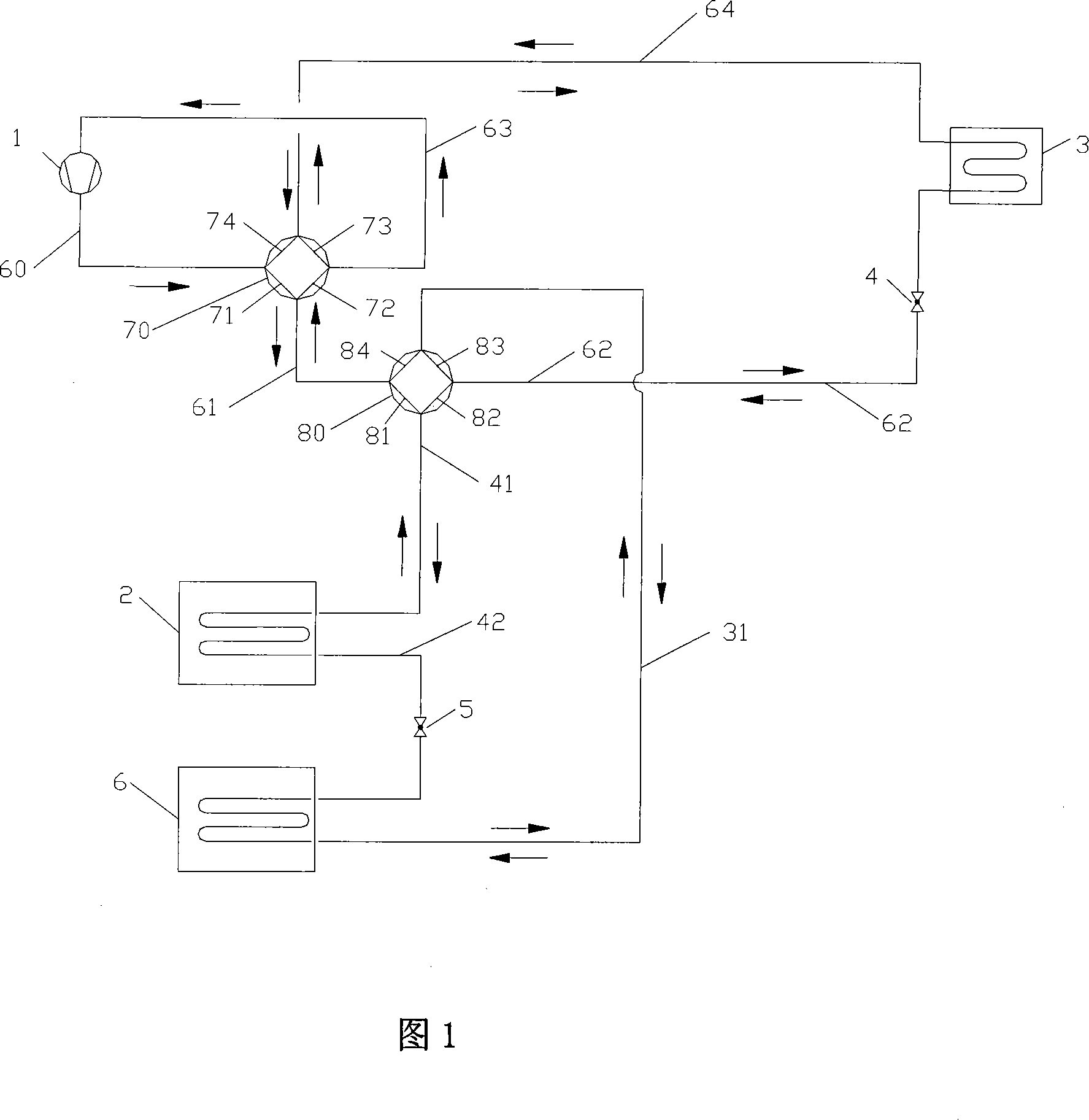
[0023] As shown in Figure 1, the whole device includes the following equipment: compressor 1, outdoor heat exchanger 2, user side heat exchanger 3, throttling mechanism (4, 5), outdoor second heat exchanger 6, four-way Valves (70, 80).

[0024] The four-way valve 70 is provided with four channels 71, 72, 73, 74, and the four-way valve 80 is also provided with four channels 81, 82, 83, 84; the user-side heat exchanger 3 can be a refrigerant-air heat exchanger , can also be a refrigerant-water heat exchanger; the outdoor heat exchanger 2 and the second outdoor heat exchanger 6 are refrigerant-air heat exchangers; the throttling mechanism (4, 5) is an electronic expansion valve.

[0025] The whole device can be divided into three circulation systems according to the different working processes: summer cooling cycle, winter heating cycle, and winter defrosting cycle.

[0026] 1. Summer refrigeration cycle

[0027] In the summer refrigeration cycle, the outlet of the compressor 1...

Embodiment 2

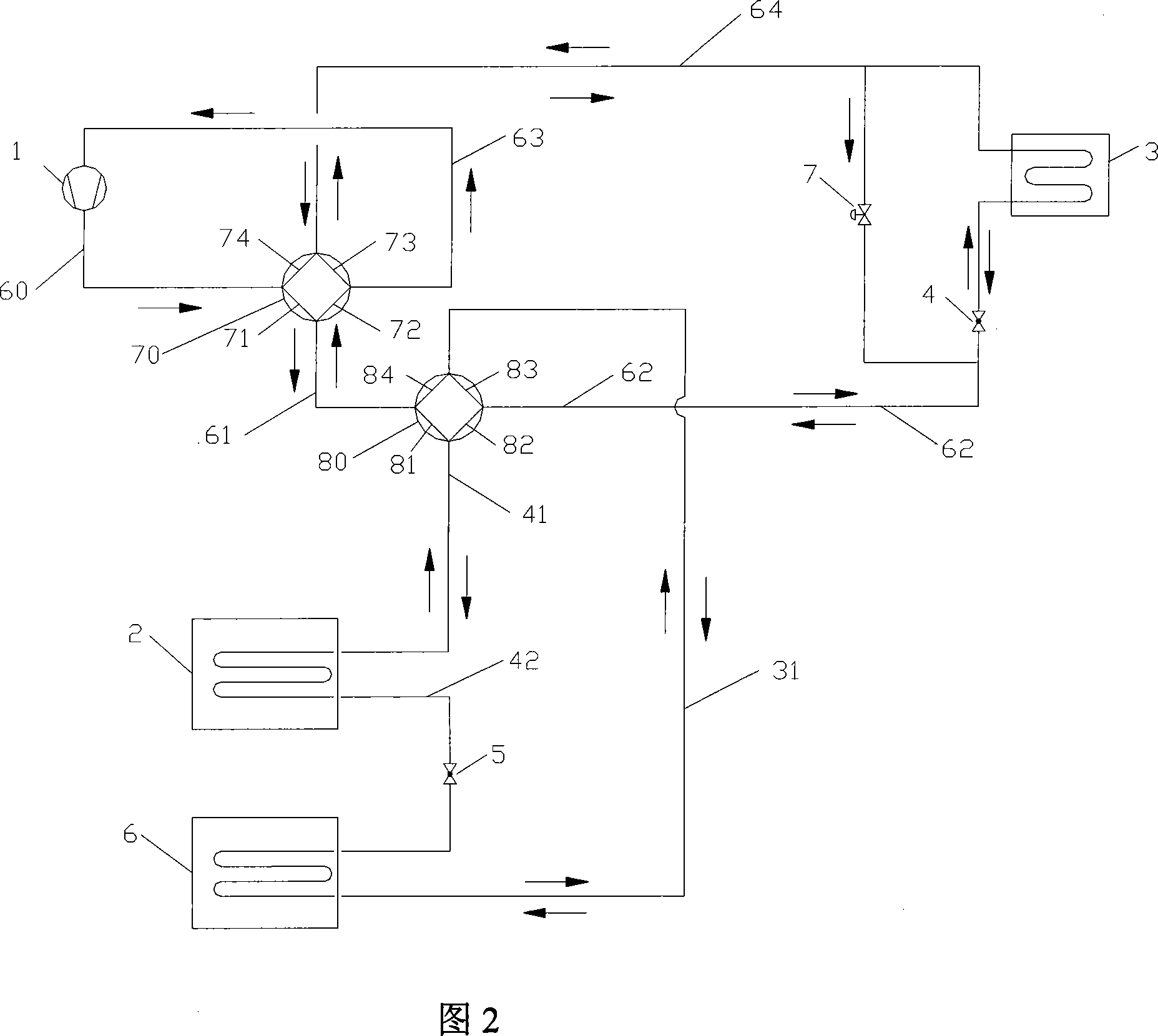
[0039] As shown in Figure 2, compared with Embodiment 1, the only difference is that the flow direction control valve 7 is added, which is connected in parallel with the user-side heat exchanger 3 and the throttling mechanism 4, while other equipment and connection methods in the device Exactly the same as Example 1.

[0040] During the working process of the cooling cycle in summer and the heating cycle in winter in embodiment 2, the flow direction control valve 7 is closed, so the working process of the cooling and heating cycle in embodiment 2 is exactly the same as that in embodiment 1.

[0041] During the working process of the winter defrosting cycle in Example 2, the flow direction control valve 7 is opened, and the throttling mechanism 4 is closed. Therefore, during the defrosting process, the refrigerant superheated vapor from the compressor 1 does not pass through the user-side heat exchanger 3 and the throttling mechanism 4, and bypass the flow control valve 7, so t...

Embodiment 3

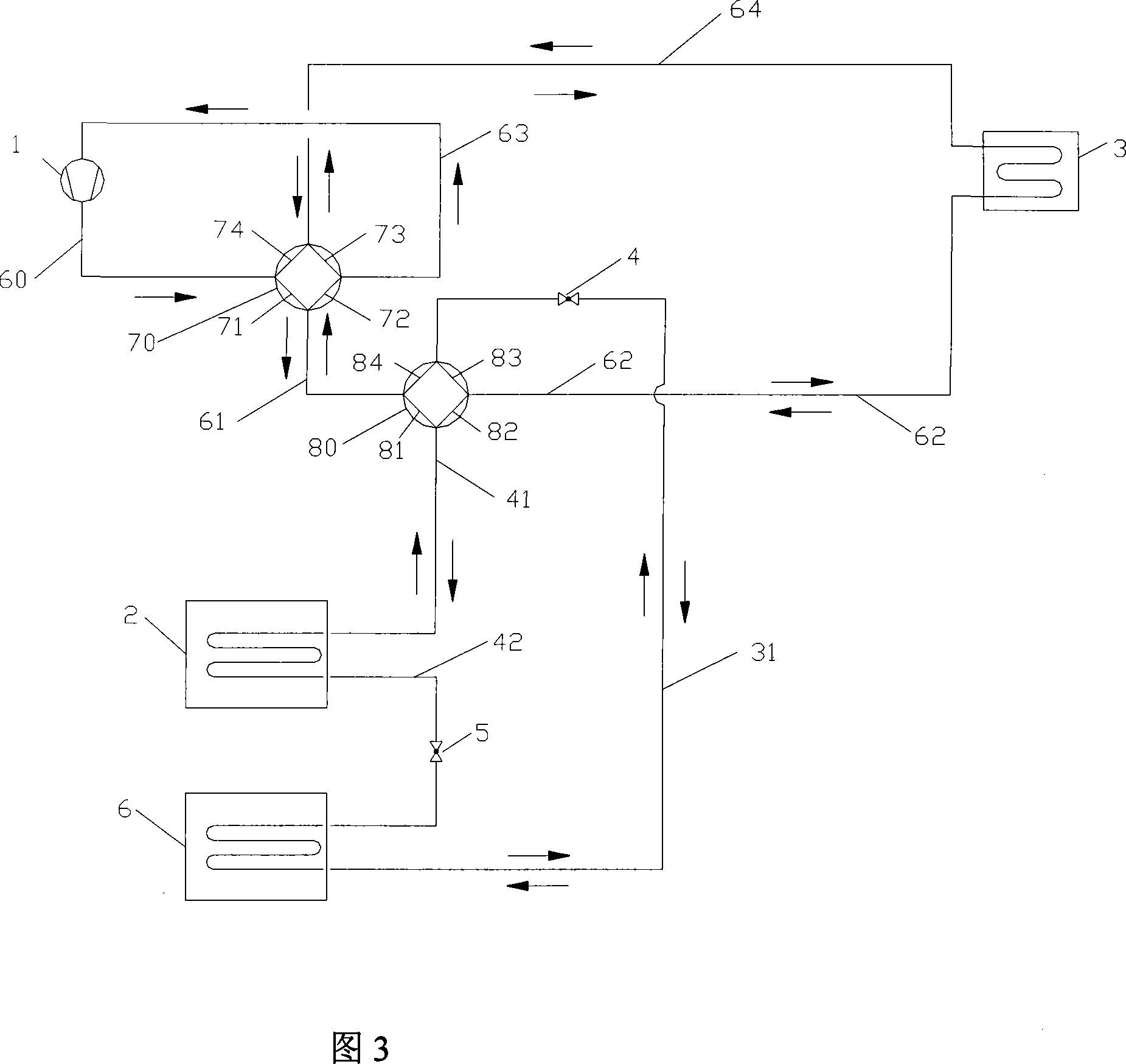
[0044] As shown in Figure 3, the difference between it and Embodiment 1 is: in Embodiment 1, the throttling mechanism 4 is arranged on the pipe connecting the user-side heat exchanger 3 and the four-way valve 80; but in Embodiment 3 , the throttling mechanism 4 is set on the pipeline connecting the second outdoor heat exchanger 6 and the four-way valve 80 , that is, the channel through which the outdoor second heat exchanger 6 passes through the pipeline 31 , the throttling mechanism 4 and the four-way valve 80 (83,84) are connected.

[0045] Apart from that, in Embodiment 3, other devices are connected in the same way as in Embodiment 1. During operation, the functions and working process of each device are also the same as in Embodiment 1.


PUM


Abstract

This invention discloses an air-source thermal pump device used in summer and winter including a compressor, an outdoor heat-exchanger, a user heat-exchanger, a throttle unit and a four-way valve. This invention adds an outer door second heat exchanger, a throttle unit and a four-way valve, which absorbs heat from outdoor air when defrosting in winter to realize defrosting to hot gas and avoid counteract of cold and hot volume and reduce energy cost in the process and increase performance of hot pump device, besides, this invention can realize super-cooling of cooling agent.

Description

technical field [0001] The invention relates to a dual-purpose air source heat pump device for winter and summer, which belongs to the technical field of refrigeration. Background technique [0002] At present, the conventional winter and summer dual-purpose air source heat pump device is composed of a compressor, a user-side heat exchanger, an outdoor heat exchanger, a throttling mechanism and a four-way valve. It relies on the four-way valve to switch between winter and summer operating conditions. Provide cooling for users and heat for users in winter. [0003] During the operation of this heat pump device in winter, when the evaporation temperature is lower than 0°C, frost will form on the outdoor heat exchanger, which will affect the normal operation of the heat pump device. Therefore, it must be defrosted regularly during operation. The most commonly used defrosting method is reverse cycle hot gas defrosting. This method can ensure rapid and effective defrosting. Howe...

Claims


Application Information

Patent Timeline
Patent Type & Authority Applications(China)
IPC IPC(8): F25B13/00F25B30/02F25B47/02
Inventor 刘雄
Owner XI'AN UNIVERSITY OF ARCHITECTURE AND TECHNOLOGY
Why Eureka
Try Eureka