
Cold-producing medium loop

A refrigerant circuit, refrigerant technology, applied in refrigerators, refrigeration and liquefaction, lighting and heating equipment, etc., can solve problems such as poor space efficiency, and achieve the effect of preventing pressure rise

Inactive Publication Date: 2008-01-02
FUJI ELECTRIC RETAIL SYST CO LTD
View PDF1 Cites 21 Cited by
  • Summary
  • Abstract
  • Description
  • Claims
  • Application Information

AI Technical Summary

Problems solved by technology

In conventional gas-liquid separators, space efficiency is poor because it is formed in a tank shape with a volume for temporarily storing mixed refrigerant
In particular, when evaporators are respectively arranged in a plurality of commodity storages as in the above-mentioned automatic vending machines, and each evaporator operates separately, in order to prevent the refrigerant circulation amount from changing due to the difference in the number of operating evaporators, Liquid compression occurs in the compressor, it is necessary to enlarge the tank

Method used


Image

  • Cold-producing medium loop
  • Cold-producing medium loop
  • Cold-producing medium loop

Examples


Embodiment Construction

[0106] Next, preferred embodiments of the refrigerant circuit of the present invention will be described in detail with reference to the drawings. However, the present invention is not limited by these embodiments.

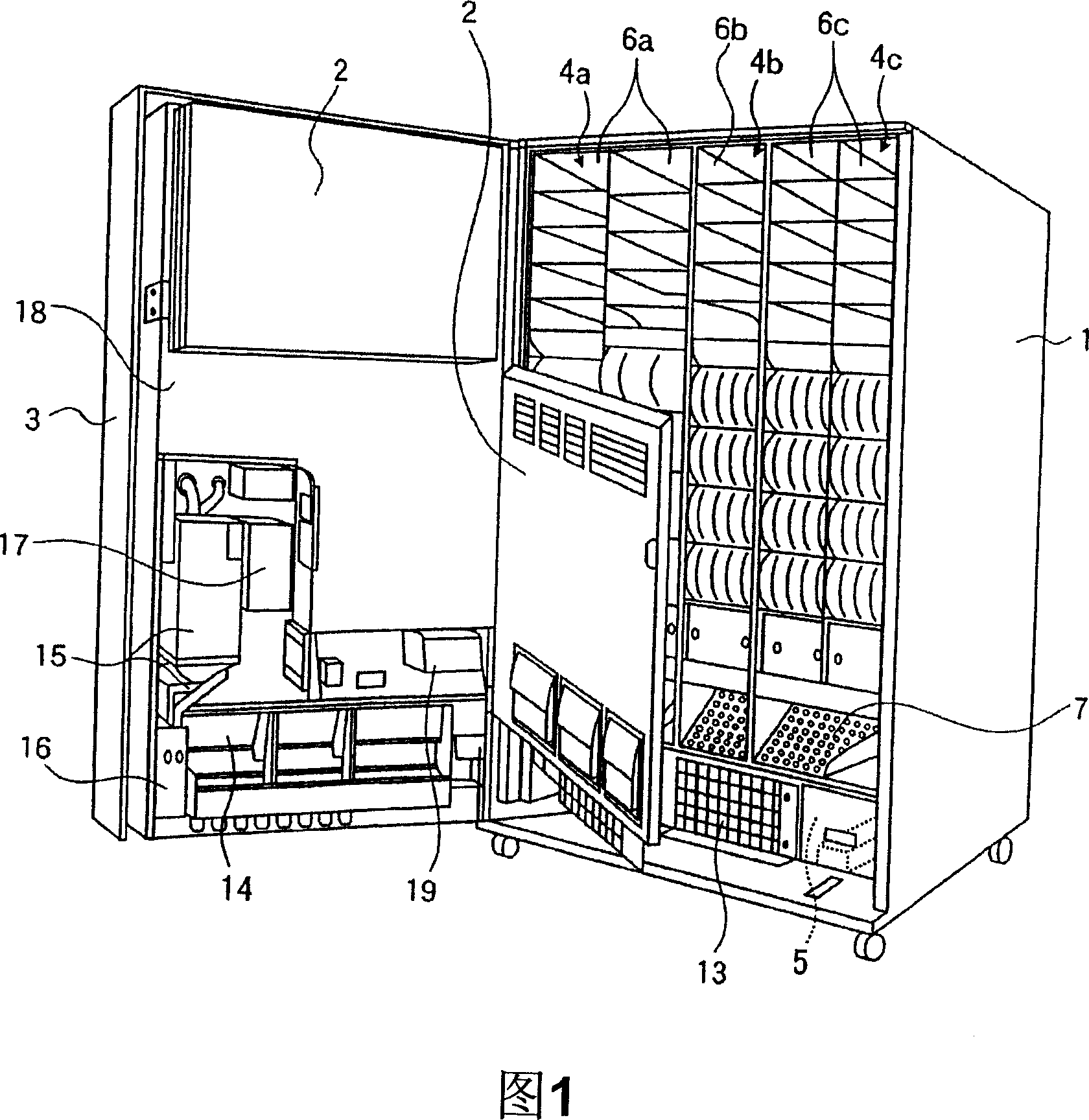
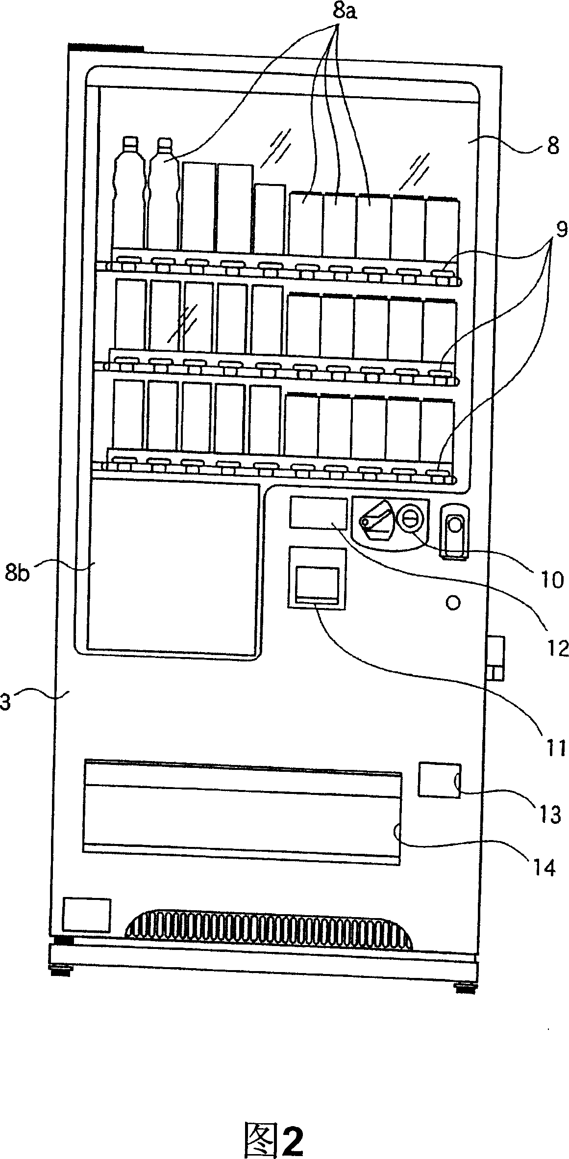
[0107] First, a vending machine suitable for use with the refrigerant circuit of the present invention will be described. Fig. 1 is a perspective view showing an open interior state of an automatic vending machine to which the refrigerant circuit of the present invention is suitable. Fig. 2 is a front view of the vending machine shown in Fig. 1 .

[0108] The automatic vending machine shown here is used to sell commodities such as canned beverages or PET bottled beverages, and includes a main body box 1, an inner door 2 and a main door 3 as shown in FIG. 1 .

[0109] As for the main body box 1, it is constructed firmly by proper combination of a plurality of steel plates, and the front becomes an open rectangle. Inside the main body box, three commodity storage...


PUM


Abstract

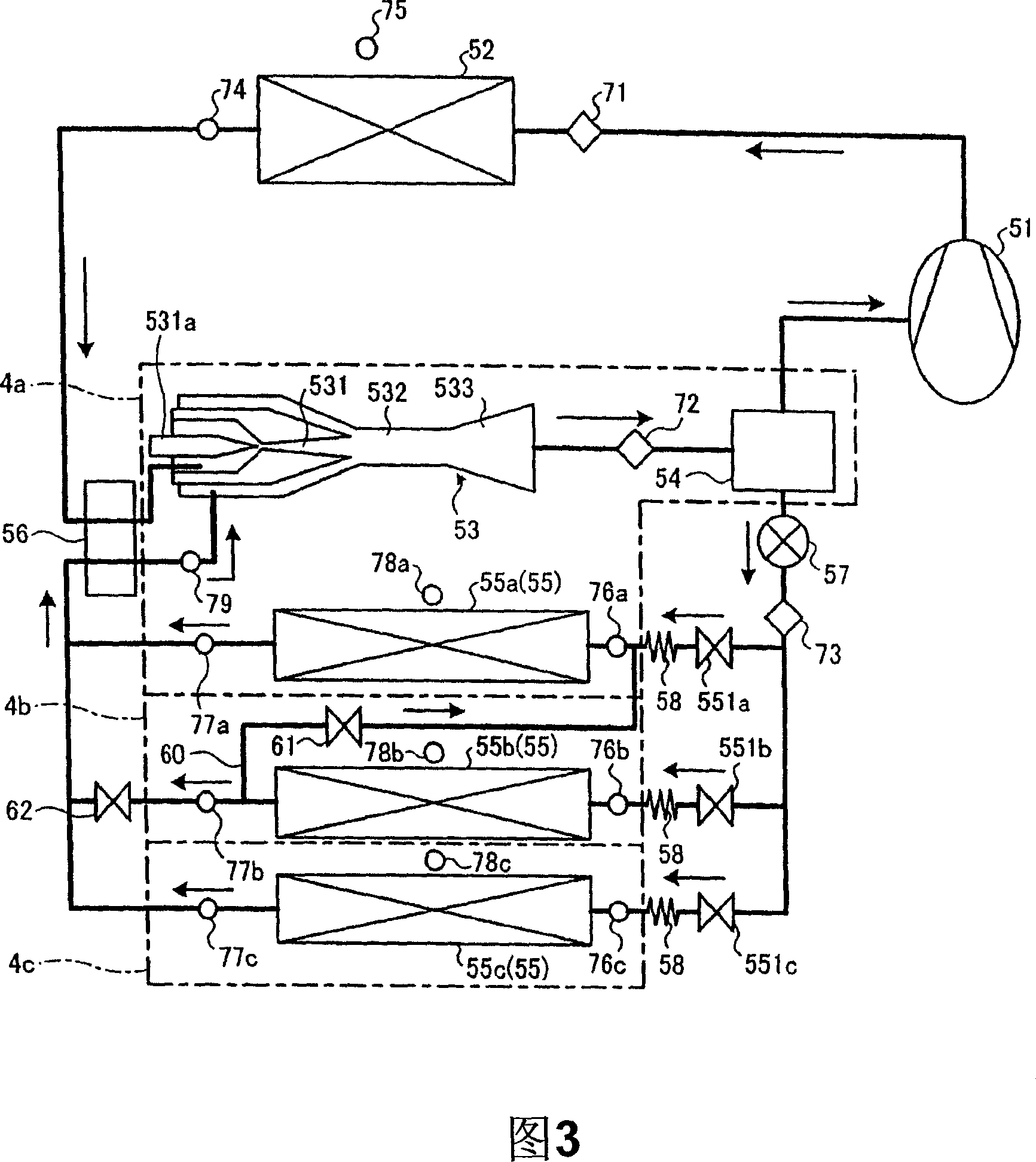
The invention discloses a cooling agent circuit, which is characterized by the following: comprising compressor of compression refrigerating agent, gas cooler, evaporator to evaporate cooling agent, ejector and inner heat exchanger; depressing high pressure cooling agent from gas cooler; absorbing in the low pressure cooling agent from the evaporator; mixing; increasing the pressure for mixed cooling agent; discharging with the ejector; separating the mixed cooling agent to gas phase cooling agent and liquid phase cooling agent; turning the gas phase back to the compressor; providing the liquid phase cooling agent to the gas-liquid separator of the evaporator; paralleling the multiple evaporator; connecting multiple strips of cooling agent cycling passage through switch valve; proceeding heat exchange for the high pressure cooling agent and the low pressure cooling agent with the inner heat exchanger. This invention can prevent increasing of high pressure side, which can make the cycling state to reach optimum.

Description

technical field [0001] The present invention relates to refrigerant circuits, and more particularly to refrigerant circuits using ejectors. Background technique [0002] Conventionally, a refrigeration cycle has been disclosed as a refrigerant circuit. The refrigeration cycle is sequentially connected to a compressor, a condenser, a two-phase flow ejector, and a gas-liquid separator, and is installed between the suction port of the ejector and the refrigerant liquid retention part of the gas-liquid separator through a throttling device. There is an evaporator. For this refrigeration cycle, the ejector circulates the low-pressure refrigerant through the suction effect generated by the injection energy (driving flow) of the high-pressure refrigerant from the condenser, reducing the evaporation temperature and improving the heat exchange efficiency while reducing the compressor's Amount of work (for example, see Patent Document 1). [0003] [Patent Document 1] Japanese Paten...

Claims


Application Information

Patent Timeline
Patent Type & Authority Applications(China)
IPC IPC(8): F25B9/08
Inventor 久保山公道土屋敏章滝口浩司
Owner FUJI ELECTRIC RETAIL SYST CO LTD
Learn More