External joint part of a synchronous rotating joint for a wheel hub unit

A constant-speed universal joint and external joint technology, applied in the direction of rotating parts, wheel hubs, vehicle parts, etc., which are resistant to centrifugal force, and can solve problems such as wear and noise

Active Publication Date: 2008-01-02
GKN DRIVELINE DEUTSCHLAND GMBH
View PDF0 Cites 7 Cited by
  • Summary
  • Abstract
  • Description
  • Claims
  • Application Information

AI Technical Summary

Problems solved by technology

This leads to the formation of noise and wear

Method used


Image

  • External joint part of a synchronous rotating joint for a wheel hub unit
  • External joint part of a synchronous rotating joint for a wheel hub unit
  • External joint part of a synchronous rotating joint for a wheel hub unit

Examples


Embodiment Construction

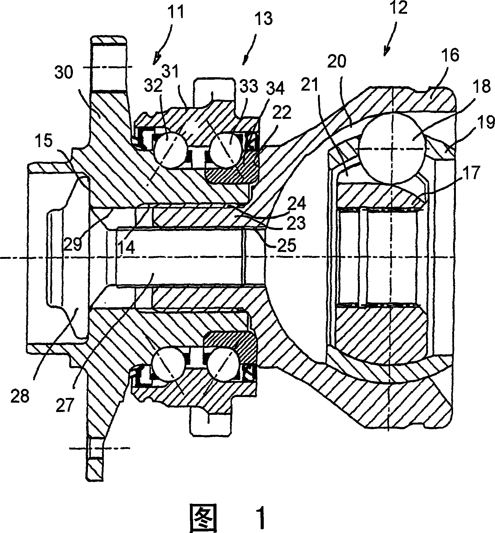
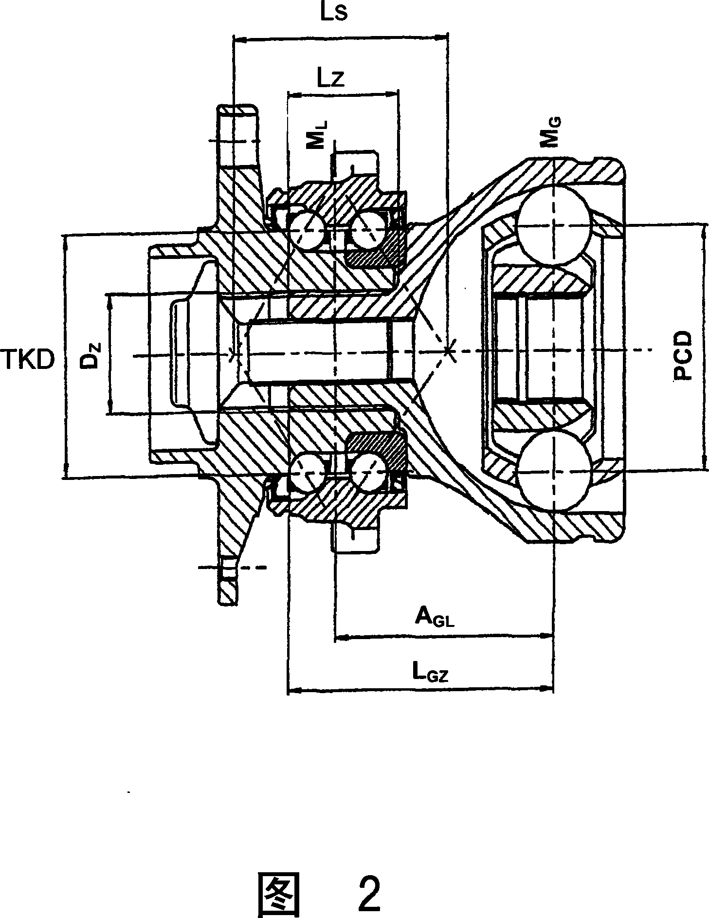
[0022] Figures 1 and 2 each show a hub unit 11 for a drive wheel of a motor vehicle, which has a constant speed fixed joint 12 connected to a drive shaft. The hub unit 11 includes a hub 30 and a bearing unit 13, wherein the bearing unit 13 is slidably fitted to the hub 30 and clamped between the hub 30 and the constant-speed fixed joint 12 in the axial direction. The hub 30 includes a flange screwed to a wheel, and a brake disc can also be screwed to the wheel. In addition, the hub 30 includes a through hole 29, and the inner shaft teeth 14 are formed into the through hole from the joint end. A support surface 15 which is located in the center and is substantially radial is formed on the flange. The constant speed fixed joint 12 is arranged in the form of a UF joint (no undercut joint), and includes an outer joint part 16, an inner joint part 17, a torque transmission ball 18 and a ball cage 19. The balls are held and guided in the outer ball track 20 in the paired outer joint par...


PUM


Abstract

An external joint part of a wheel hub synchronous fixed joint unit, wherein a wheel hub (60,90) provided with a through-opening (59,89), which includes inner corrugated toothing (54,84), is tensed with the external joint part (46,76) of a synchronous rotating joint (42,72), upon which a journal (53, 83) having outer corrugated toothing (54, 84) is formed, wherein the inner corrugated toothing (44, 74) of the through-opening (59, 89) and the outer corrugated toothing (54, 84) of the journal (53, 83) engage with each other, and a two-row wheel bearing (43, 73) is placed onto the wheel hub (60, 90), comprising an inner bearing ring (64, 94) upon which a front surface (52, 82) of the external joint part (46, 76) rests directly, wherein the ratio of the journal diameter on the base of the journal DZ and the length of the journal Lz is greater than 0.95, i.e. Dz / Lz > 0.95.

Description

Technical field [0001] The invention relates to an outer joint part for a wheel hub-constant speed fixed joint-unit, in which a hub with a through hole with inner shaft teeth is clamped to the outer joint part of a constant speed universal joint On the above, a journal with outer shaft teeth is formed on the outer joint part, wherein the inner shaft teeth of the through hole and the outer shaft teeth (54, 84) of the journal mesh with each other, and a double row wheel bearing is slidingly fitted On the hub, the bearing of the wheel includes an inner bearing race, which directly supports one end surface of the outer joint component. This type of assembly is used for the steering wheel of a driven, more specifically, a motor vehicle, in which the wheel and a brake disc are threadedly connected to the flange of the wheel hub, and the constant-speed universal joint forms a drive shaft ( The side shaft) is an integral part of the transmission shaft. The transmission shaft can be compos...

Claims


Application Information

Patent Timeline
Patent Type & Authority Applications(China)
IPC IPC(8): B60B27/00
CPCB60B27/00Y10S464/906F16D3/223F16D2003/22326F16D2001/103
Inventor H·色马克
Owner GKN DRIVELINE DEUTSCHLAND GMBH
Why Eureka
Try Eureka