Monitoring camera device, monitoring system using the same, and monitoring image transmission method

A technology for monitoring cameras and images, applied in telemetry/remote control selection devices, transmission systems, image communications, etc., can solve the problem of increasing the amount of transmitted data, and achieve the effect of suppressing load and improving accuracy

Inactive Publication Date: 2008-01-02
PANASONIC CORP
View PDF3 Cites 10 Cited by
  • Summary
  • Abstract
  • Description
  • Claims
  • Application Information

AI Technical Summary

Problems solved by technology

However, when a person does not pass in front of a surveillance camera device, that is, when no abnormality is recognized at all, and if the network is overloaded, a high-quality transmission protocol is also used to transmit images that are not particularly important
As a result, the amount of transferred data increases

Method used


Image

  • Monitoring camera device, monitoring system using the same, and monitoring image transmission method
  • Monitoring camera device, monitoring system using the same, and monitoring image transmission method
  • Monitoring camera device, monitoring system using the same, and monitoring image transmission method

Examples


Embodiment approach 1

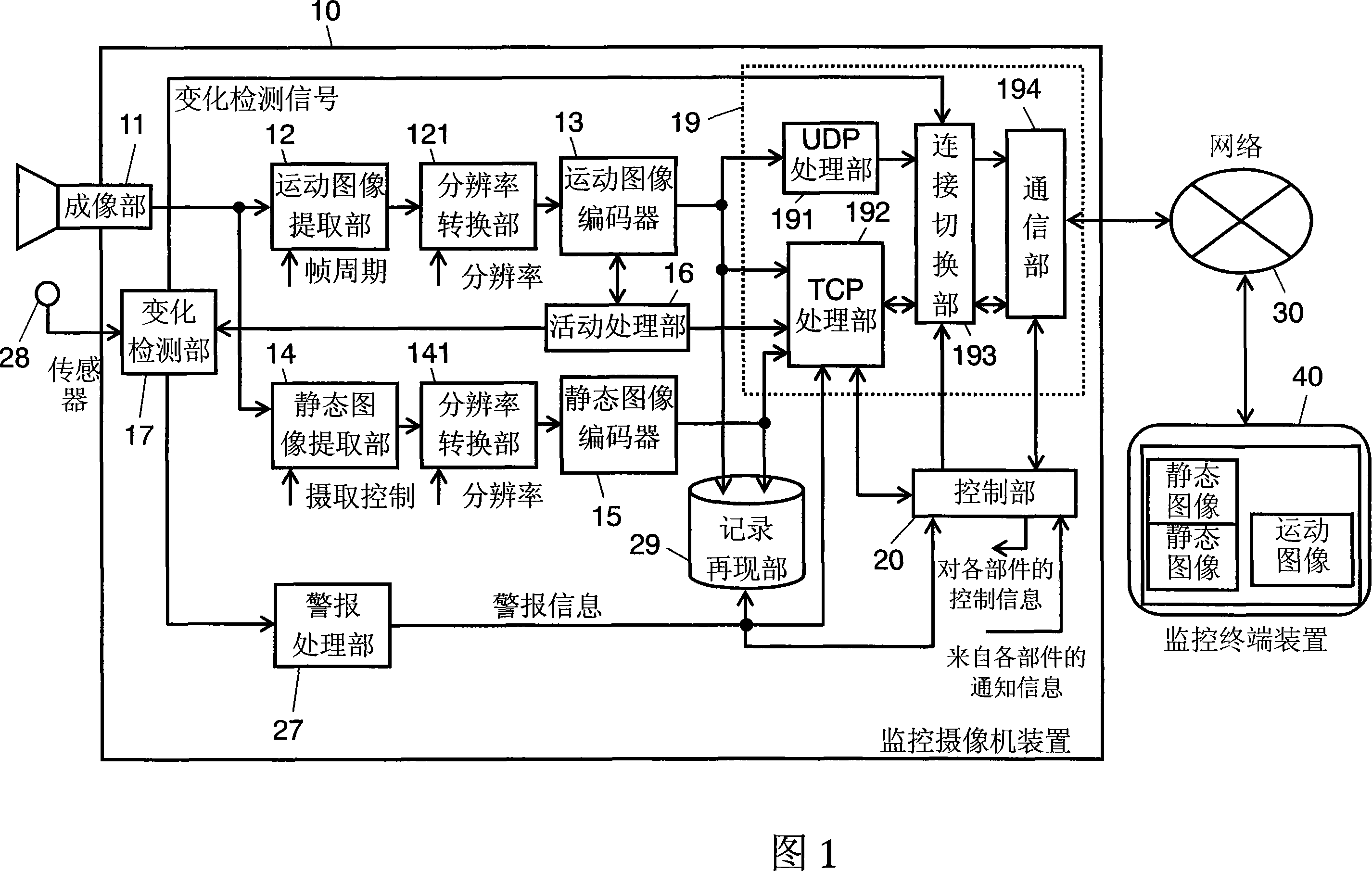
[0075] FIG. 1 is a block diagram showing the configuration of a monitoring system including a monitoring camera device according to Embodiment 1 of the present invention. As shown in FIG. 1 , in this monitoring system, monitoring is performed by observing an image of a subject captured by an imaging unit 11 serving as a monitoring camera. The monitoring system includes a monitoring camera device 10 that generates image data of a subject, a network 30 that remotely transmits image data of the subject captured by the monitoring camera device 10 , and a monitoring device that is communicatively connected to the monitoring camera device 10 via the network 30 . Terminal device 40 . In this monitoring system, the monitoring image data captured by the monitoring camera device 10 is transmitted to the monitoring terminal device 40 through the network 30 serving as a communication network. Therefore, for example, the monitor monitors the transmitted image using the monitor terminal de...

Embodiment approach 2

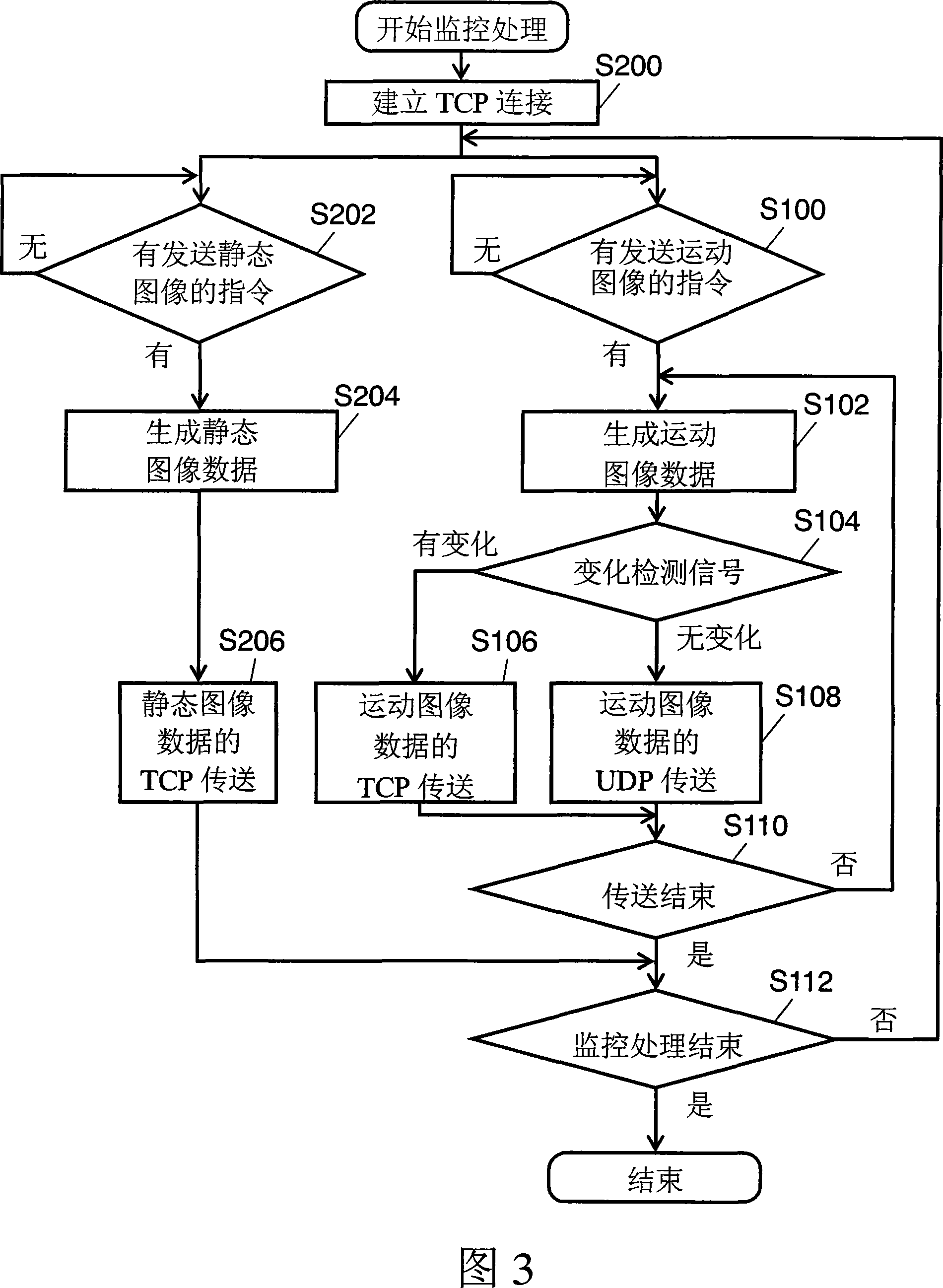
[0119] 4 is a block diagram showing the configuration of a surveillance system including a surveillance camera device according to Embodiment 2 of the present invention.

[0120] In Embodiment 2, similarly to Embodiment 1, this monitoring system performs monitoring using the subject image captured by the imaging unit 11 which is a monitoring camera. This monitoring system comprises: the monitoring camera device 10 that generates the image data of the shooting object; the network 30 that remotely transmits the image data of the shooting object captured by the monitoring camera device 10; and the monitoring terminal that communicates with the monitoring camera device 10 through the network 30 device 40. The monitoring image data captured by the monitoring camera device 10 is transmitted to the monitoring terminal device 40 via the network 30 which is a communication network. In addition, the same symbols are assigned to the same components as those in FIG. 1 , and detailed desc...


PUM


Abstract

A monitoring camera device includes a imaging unit (11) for generating image data on a monitoring object, a dynamic image extraction unit (12) for extracting image data from the image data for a predetermined frame cycle, a motion image encoder (13) for generating motion image data obtained by compressing / encoding the extracted image data, a change detection unit (17) for outputting a change detection signal indicating a change of the object, and a transmission processing unit (19) for switching between at least two types of communication protocol according to the change detection signal and performing data transmission processing. The transmission processing unit (19) transmits motion image data to the monitoring terminal device (40) via a network (30) according to a connectionless communication protocol if the change detection signal indicates that there is no change and according to a connection type communication protocol if the change detection signal indicates that there is a change. With this configuration, it is possible to provide a monitoring camera device and a monitoring system capable of appropriately transmitting an image required for judging whether a monitoring object is abnormal.

Description

technical field [0001] The present invention relates to a monitoring camera device for remote monitoring using an image of a subject captured by a monitoring camera, etc., and a monitoring system using the monitoring camera device, and more particularly to remote monitoring of the image data of the captured image of the subject using a network or the like. A monitoring system for transmission, a monitoring camera device and a monitoring image transmission method utilized in the system. Background technique [0002] Hitherto, various technologies related to surveillance camera devices or surveillance systems have been proposed. Especially in recent years, a monitoring system for monitoring by transmitting image data captured by a monitoring camera installed in a monitoring place to a remote monitor by using a network such as the Internet, and a monitoring camera device used in the monitoring system have been proposed. related technologies. These technical contents are discl...

Claims


Application Information

Patent Timeline
Patent Type & Authority Applications(China)
IPC IPC(8): H01L29/06G08B25/00H04N7/18H04Q9/00H04L29/06
CPCG08B13/19663H04L67/125G08B13/19656H04L67/025H04N7/185
Inventor 松田圭右樋口学获野亮司
Owner PANASONIC CORP
Why Eureka
Try Eureka