Injection moulding machine automatic taking off mechanism

An injection molding machine and automatic technology, applied in the field of injection molding machines, can solve problems such as adhesion and workpiece deformation

Inactive Publication Date: 2008-01-09
蔡佳祎
View PDF0 Cites 19 Cited by
  • Summary
  • Abstract
  • Description
  • Claims
  • Application Information

AI Technical Summary

Problems solved by technology

At the same time, it overcomes the problems of workpiece deformation and adhesion caused by direct drop on the mold

Method used


Image

  • Injection moulding machine automatic taking off mechanism
  • Injection moulding machine automatic taking off mechanism
  • Injection moulding machine automatic taking off mechanism

Examples


Embodiment Construction

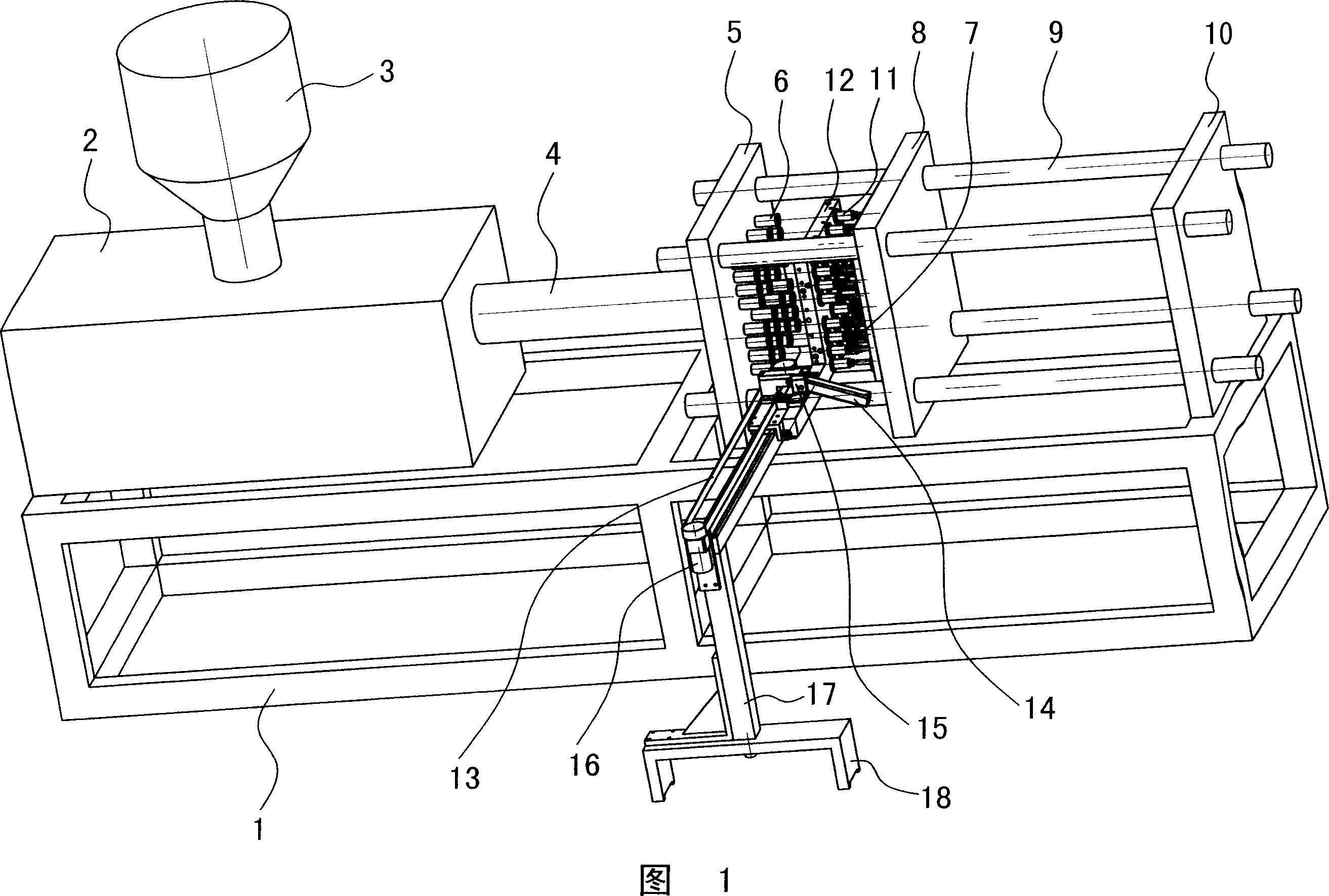
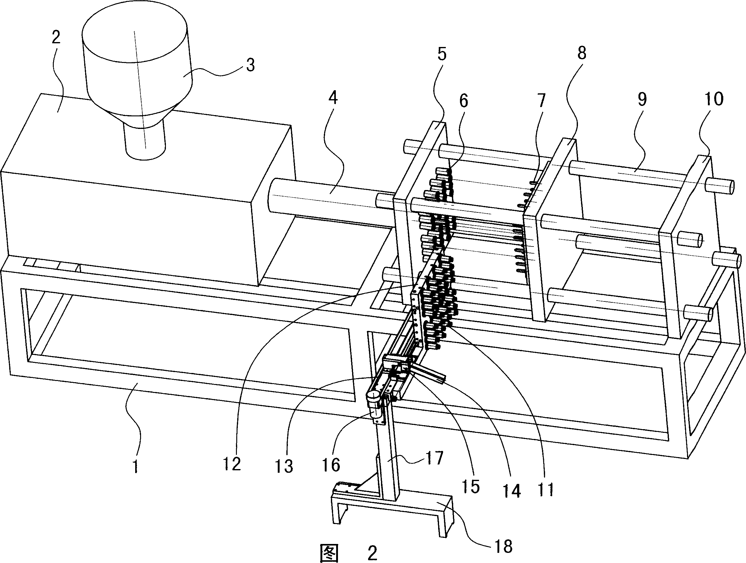
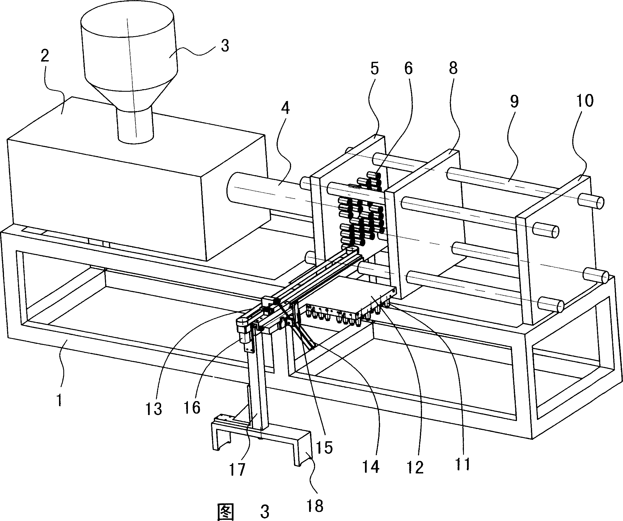
[0010] The invention relates to an automatic take-out mechanism of an injection molding machine. After the injection molding machine completes injection molding, the take-out mechanism enters between the fixed template and the movable template to take out the injection molded workpiece, so as to realize fully automatic production without manually taking the workpiece, as shown in Figures 1-4 , is an injection molding machine frame 1, the injection molding machine integral seat 2 and the heating barrel 4 are installed on the frame 1, the hopper 3 is connected to the integral seat 2, and the fixed template 5 and the movable template are installed on the frame at the same time 8. Rear formwork 10, etc., but the fixed formwork 5 on the frame is connected to the movable formwork 8 and the rear formwork 10 through the guide column 9, and the fixed formwork 5 and the movable formwork 8 are equipped with molds 6 and 7, that is, bottle tube molds 6 and 7, Above-mentioned structure is id...


PUM


Abstract

The automatic injection molded workpiece unloading mechanism for plastic injection molding machine with frame, integral seat, material heating bin, etc includes one fixed mold plate, one movable mold plate, one mold, one unloading plate with unloading mold, one reciprocator connected to the unloading plate and one unloading device. After injection molding, the fixed mold plate and the movable mold plate are opened, the unloading plate under the action of the reciprocator enters to between the fixed mold plate and the movable mold plate, the unloading mold accepts the molded workpiece pushed out by the demolding mechanism in the movable mold, and the unloading plate with the molded workpiece is withdrawn from between the fixed mold plate and the movable mold plate, so as to complete the molded workpiece unloading. The automatic unloading process is fast and high in efficiency.

Description

technical field [0001] The present invention relates to an injection molding machine, in particular to a mechanism for automatically taking out molded products after the injection molding machine completes injection molding, such as bottle tubes or other molded plastic products. Background technique [0002] When the plastic machine is processing the product, it needs to take out the molded product from the mold after the injection molding is completed, especially a multi-cavity product, such as the production of mineral water bottle tubes, or other plastic products. The existing method is manually taken out from the mould, which has the following disadvantages: the first is long downtime, low work efficiency and slow speed; the second is high labor intensity, especially in summer; the third is easy to cause industrial accidents. Some existing methods are to directly eject the workpiece on the injection mold to make the workpiece fall, but because the workpiece is soft after...

Claims


Application Information

Patent Timeline
IPC IPC(8): B29C45/40
Inventor 蔡佳祎
Owner 蔡佳祎
Why Eureka
Try Eureka