
Multifunctional pressing type water-saving closet

A toilet, multi-functional technology, applied in the field of sanitary ware, can solve the problems of low pressure, occupation, complex structure, etc., and achieve the effect of saving tap water

Inactive Publication Date: 2008-01-09
杨春杰
View PDF1 Cites 7 Cited by
  • Summary
  • Abstract
  • Description
  • Claims
  • Application Information

AI Technical Summary

Problems solved by technology

The main disadvantage of this method is that its structure is relatively complicated, with a series of pressure transmission levers, which occupy a large space
More importantly, the pressure obtained by this method is less, and the effect of flushing the toilet is not ideal, especially when children use it, the effect is even worse
In addition, simply using domestic waste water to flush toilets cannot fully meet the needs of toilet flushing.

Method used


Image

  • Multifunctional pressing type water-saving closet
  • Multifunctional pressing type water-saving closet
  • Multifunctional pressing type water-saving closet

Examples


Embodiment Construction

[0020] The present invention will be described in detail below in conjunction with the accompanying drawings.

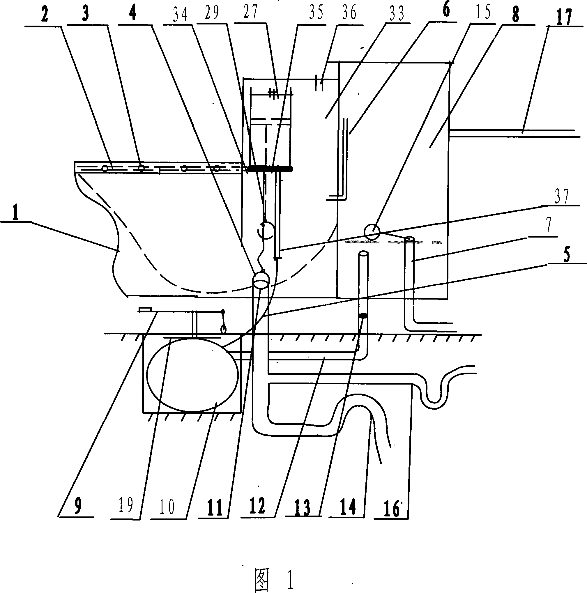
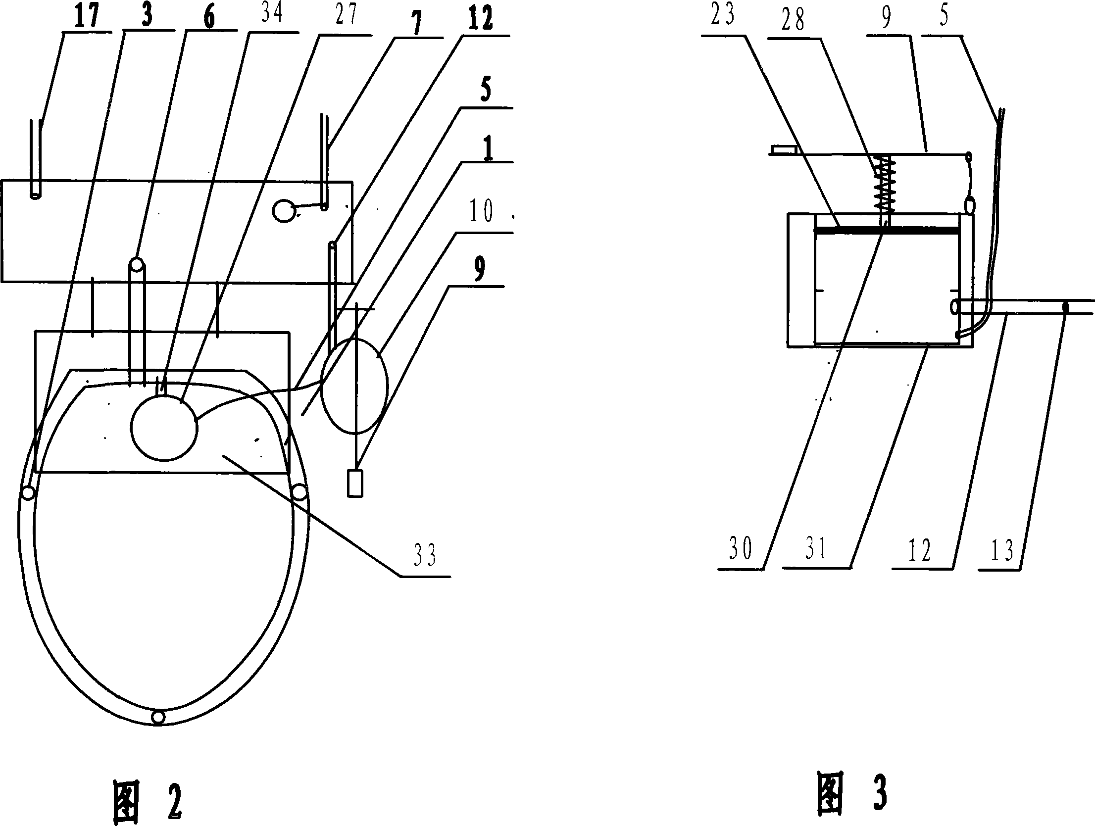
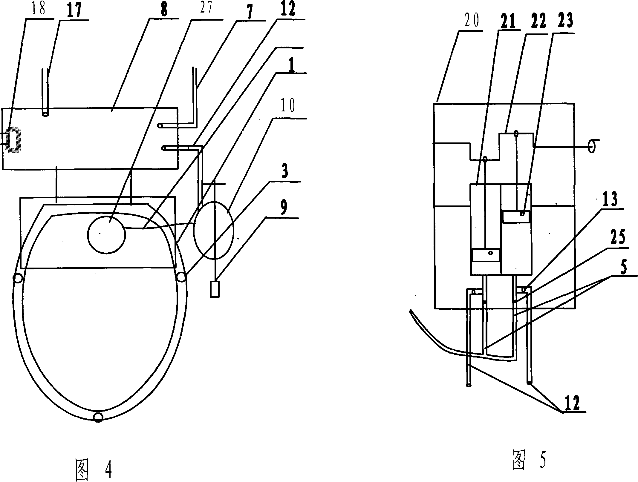
[0021] With reference to Fig. 1-2, the utility model multifunctional pressurized sewage utilization toilet has a toilet main body 1, a water spray pipe 2 is fixed on the inner side of the upper edge of the toilet main body, and the water spray pipe is distributed with Spout 3. The toilet main body rear portion is connected with water tank 8, and a waste water inlet pipe 17 is arranged on the top of water tank 8, and this water inlet pipe 17 connects the drainpipe of washing room water and the outlet pipe of rainwater tank. The bottom of water tank 8 also has a tap water inlet pipe 7, i.e. common water closet upper water pipe system. A supercharger is connected on the pipeline between the toilet main body 1 and the water tank 8 , and the pressure water pipe 5 of the supercharger is connected with the water spray pipe 2 through a float opener 27 .

[0022] The float ...


PUM


Abstract

This is a toilet using waste water which is led into water box and wash out by manpower pressure.

Description

technical field [0001] The invention relates to a sanitary ware, in particular to a toilet which can flush the toilet with washing waste water and control the water consumption. Background technique [0002] In the flushing device in the current sanitary ware toilet, the water pressure comes from the water pressure difference formed by the height of the water surface, that is, the gravity difference, the pressure is very small, and the flushing effect is poor. Therefore, a large amount of water is required to flush. Although a variety of devices for flushing toilets using waste water have been invented in recent years, and a large amount of running water has been significantly saved, the original method of flushing toilets by using the dead weight of water has not changed, and therefore, a huge waste of water will still be caused. Chinese patent 01224882 discloses: a low-position, high-pressure lifting and swirling medium waste water flushing device, which has changed the ab...

Claims


Application Information

Patent Timeline
Patent Type & Authority Applications(China)
IPC IPC(8): E03D3/10E03D1/30E03C1/12F04B9/14
Inventor 杨春杰
Owner 杨春杰
Learn More