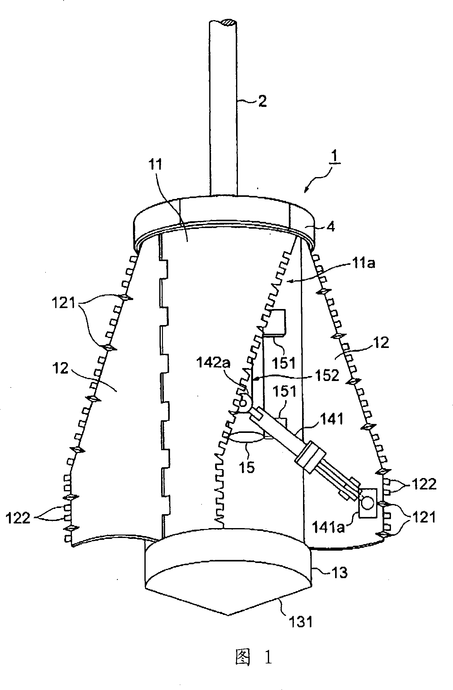
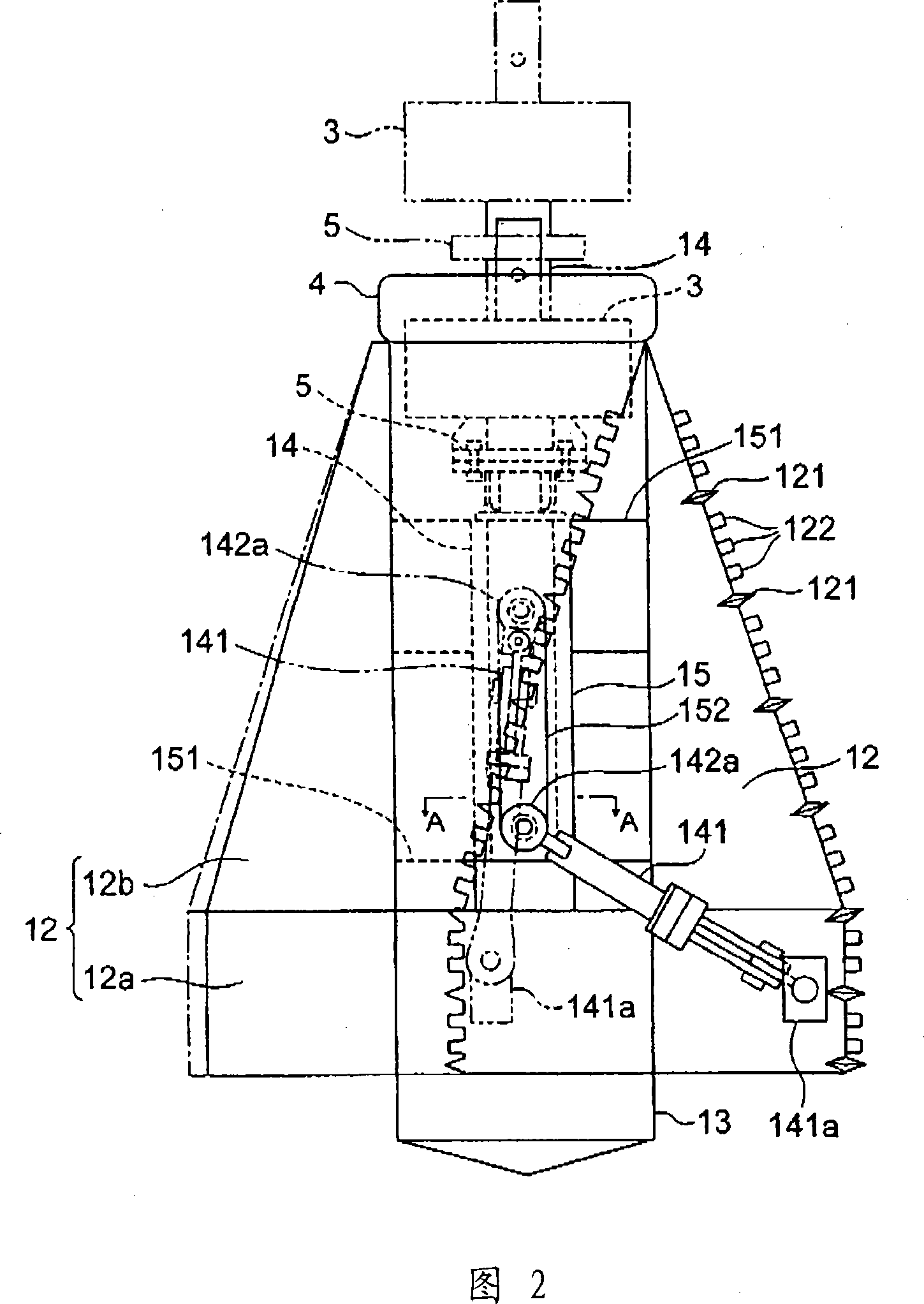
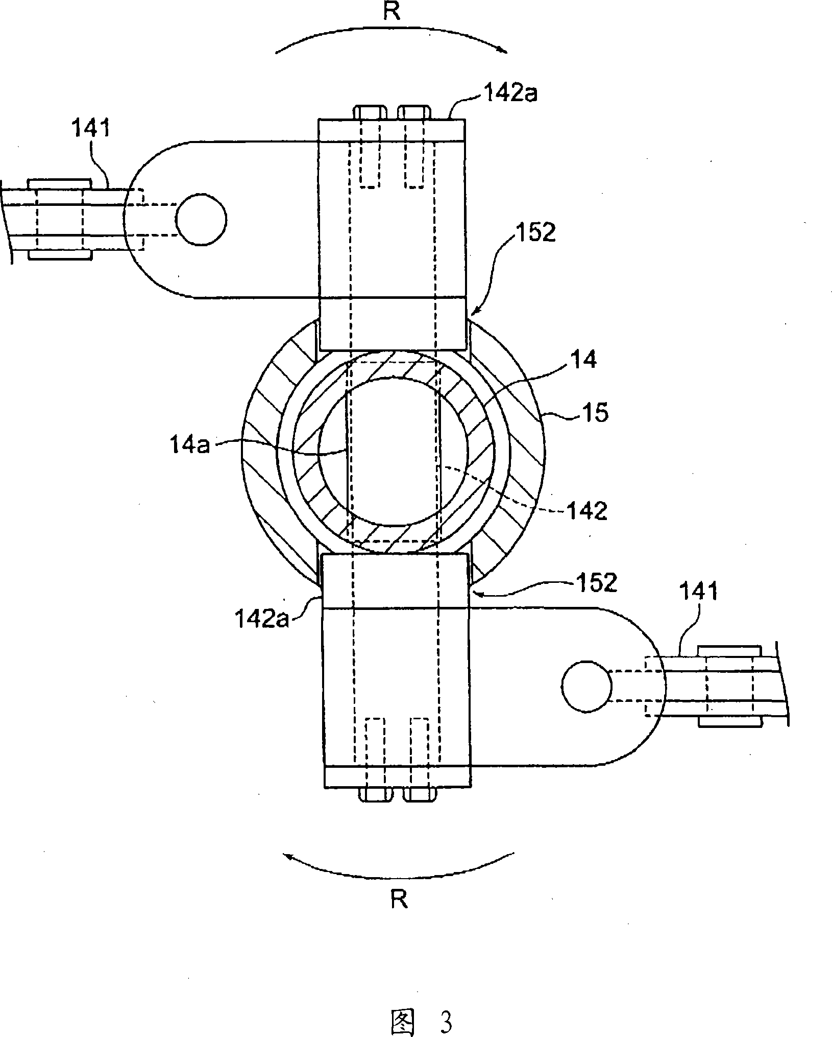
Bottom enlarging basket bucket
A technology with enlarged diameter and wings, which is applied to drilling equipment, sheet pile walls, earthwork drilling and mining, etc., and can solve problems such as many hard strata and difficult cutting of bottom expansion buckets
- Summary
- Abstract
- Description
- Claims
- Application Information
AI Technical Summary
Problems solved by technology
Method used
Image
Examples
Embodiment 1
[0090] Hereinafter, Example 1 of the above-mentioned embodiment will be described. In addition, the description of the same or equivalent parts as those described in the above-mentioned embodiment will be described using the same reference numerals.
[0091] FIG. 8 is a diagram showing a state where the opening adjustment plate 7 is provided on the upper surface of the guide cylinder 15 to adjust the descending amount of the transmission shaft portion 14 .
[0092] That is to say, in the above-mentioned embodiment, the reinforcing sleeve 142a of the connecting rod 142 is brought into contact with the lower end of the slide groove 152 to expand the expansion wings 12, 12 to the maximum extent. It is not necessary to expand the expanded bottom 60b to the maximum expanded bottom 120.
[0093] Therefore, on the upper surface of the guide cylinder 15, a plate-shaped opening adjustment plate 7 having a through hole larger in diameter than the transmission shaft portion 14 can be ad...
Embodiment 2
[0101] Hereinafter, Example 2 of the above-mentioned embodiment will be described. In addition, the description of the same or equivalent parts as those described in the above-mentioned embodiment will be described using the same reference numerals.
[0102] As shown in FIG. 9, in the second embodiment, the case of using a guide cylinder 15A having a sliding groove 152A obliquely provided on the peripheral surface will be described.
[0103] The guide cylinder 15A is at least a cylindrical tube with an open top, and is fixed to the inner surface of the main body 11A via connecting plates 151A and 151B fixed to the upper and lower parts of the outer peripheral surface.
[0104] And, as shown in FIG. 9( a ) and ( b ), a sliding groove 152A inclined in a direction intersecting the axial direction is formed on the peripheral surface of the guide cylinder 15A. Wherein, Fig. 9(a) is a C-C sectional view of Fig. 9(b), and Fig. 9(b) is a side view viewed from the B-B direction of Fig...
Embodiment 3
[0111] Hereinafter, Example 3 of the above-mentioned embodiment will be described. In addition, the description of the same or equivalent parts as those described in the above-mentioned embodiment will be described using the same reference numerals.
[0112] In this third embodiment, a case where the expanded bottom portion 60b is formed in the excavated hole 60 in which the shaft portion 60a is excavated with a diameter larger than that of the main body portion 11 will be described.
[0113] In this way, when the bottom expanding bucket 1 is inserted into the excavation hole 60 having a larger diameter than the main body portion 11, since there is a gap between the main body portion 11 and the wall surface of the excavation hole 60, as shown in FIG. and the lower part are equipped with stabilizer 4 and lower stabilizer part 133 respectively, so that the center position of the main body 11 does not deviate when expanding the bottom.
[0114] That is, the 1 / 4 arc-shaped slidin...
PUM
 Abstract
Description
Claims
Application Information
 - R&D
- Intellectual Property
- Life Sciences
- Materials
- Tech Scout
- Unparalleled Data Quality
- Higher Quality Content
- 60% Fewer Hallucinations
Browse by: Latest US Patents, China's latest patents, Technical Efficacy Thesaurus, Application Domain, Technology Topic, Popular Technical Reports.
© 2025 PatSnap. All rights reserved.Legal|Privacy policy|Modern Slavery Act Transparency Statement|Sitemap|About US| Contact US: help@patsnap.com


