Photoelectric composite cable

A technology of photoelectric composite cable and optical cable, which is applied in the direction of communication cables, cables, circuits, etc., can solve the problems of high construction cost and high purchase cost, and achieve good environmental performance, save pipeline space, good laying performance and bending resistance. Effect

Inactive Publication Date: 2008-01-09
JIANGSU ETERN
View PDF0 Cites 20 Cited by
  • Summary
  • Abstract
  • Description
  • Claims
  • Application Information

AI Technical Summary

Problems solved by technology

Currently on the market, optical cables and electric cables are two different products, so they can only be laid twice, not only the purchase cost is relatively high, but also the construction cost is relatively high

Method used


Image

  • Photoelectric composite cable
  • Photoelectric composite cable
  • Photoelectric composite cable

Examples


Embodiment

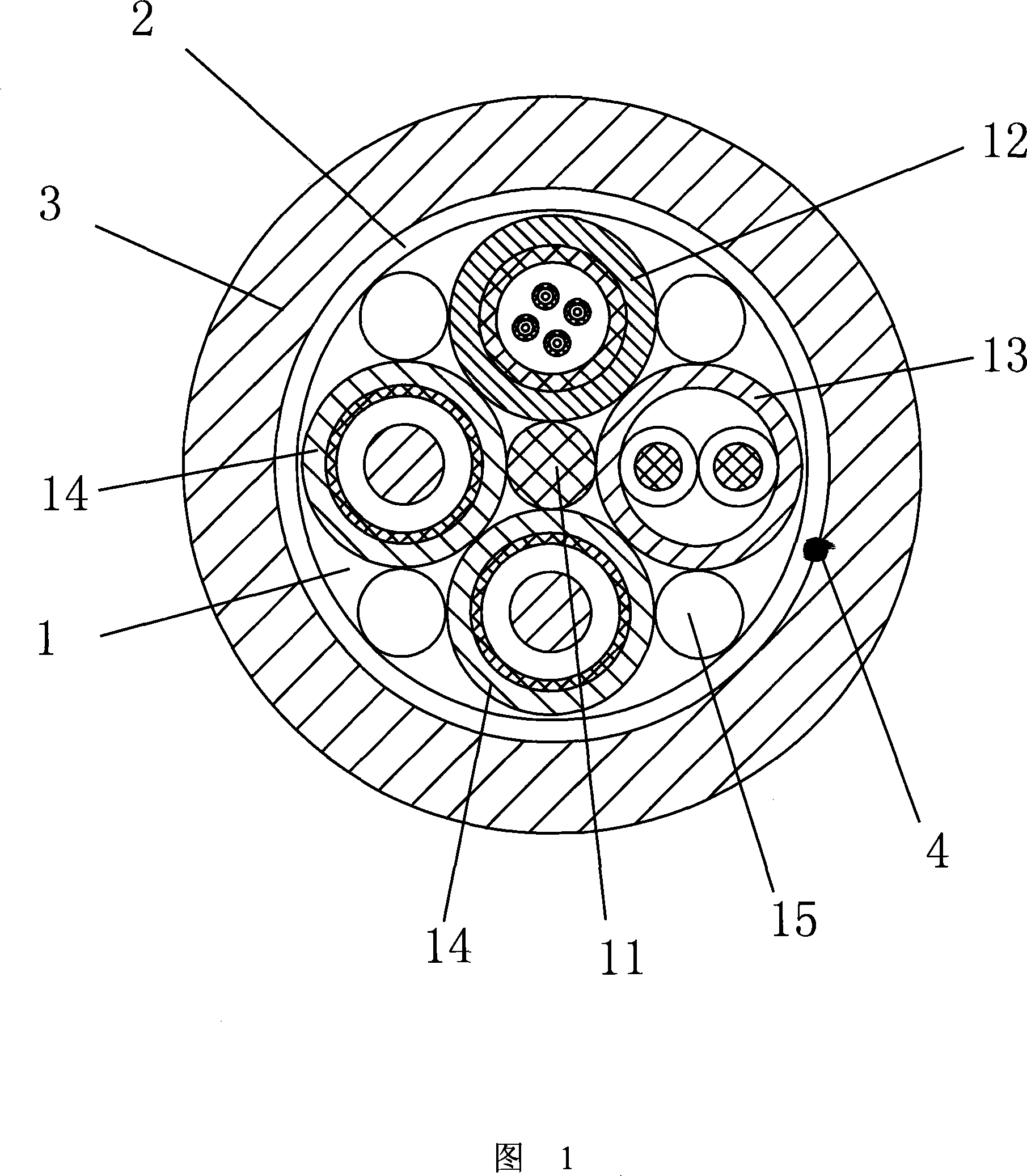
[0026] Embodiment: As shown in Figure 1, a photoelectric composite cable includes a cable core 1 with a central reinforcing member 11, a water-blocking tape 2 is provided on the outside of the cable core 1, and a sheath 3 is provided on the outside of the water-blocking tape 2, The inner wall of the sheath 3 is axially provided with a tearing rope 4 .

[0027] Cable core 1 is provided with optical cable 12 , telephone wire 13 and shielded power wire 14 around central strength member 11 , and cable core 1 is provided with filling rope 15 between optical cable 12 , telephone wire 13 and shielded power wire 14 .

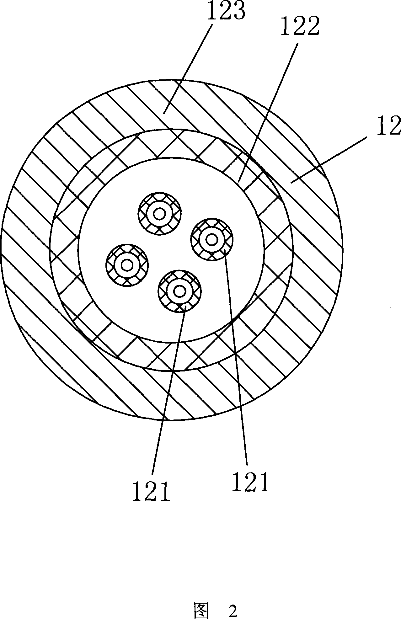
[0028] The above-mentioned optical cable 12 is one, as shown in FIG. 2 , the optical cable 12 includes a plurality of tight-buffered optical fibers 121 , the outer periphery of the plurality of tight-buffered optical fibers 121 is provided with a strengthening member 122 , and a sheath 123 is provided outside the strengthening member 122 .

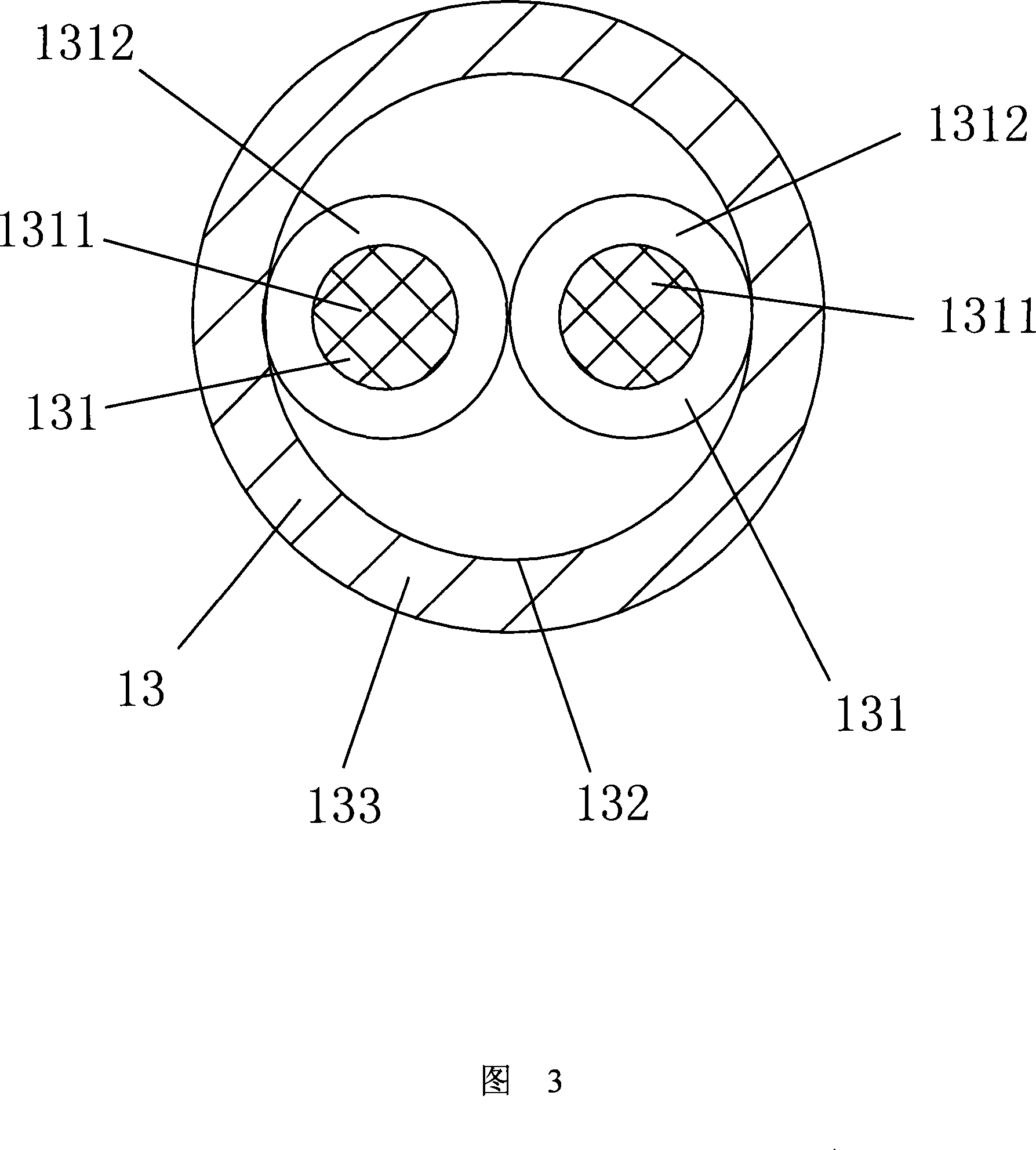
[0029] Above-mentioned telep...


PUM


Abstract

The invention is concerned with the photoelectricity composite cable, includes: the cable core that is with the central strengthening piece; sets stop-water bend outside of the cable core; sets the jacket outside of the stop-water bend; cable core sets the optical cable, the line and the screen power cord around the central strengthening piece. The invention can conformity cables that can transmit some signal, which can save the space of the channel, reduce cost, and transmit light signal and the electric signal.

Description

technical field [0001] The invention relates to a photoelectric composite cable. Background technique [0002] With the advent of the information age, the amount of information transmission has increased rapidly, and optical fiber cables have been widely used. However, in urban construction, not only optical cables, but also electrical cables are required. Currently on the market, optical cables and electric cables are two different products, so they can only be laid twice, not only the purchase cost is relatively high, but also the construction cost is relatively high. Contents of the invention [0003] The purpose of the present invention is to provide a non-metallic reinforced photoelectric composite cable that can be used for laying in urban buildings for indoor network wiring. It integrates cables that transmit several signals, is easy to install, and can transmit electrical signals at the same time. And optical signal, the overall cost of the composite cable is low...

Claims


Application Information

Patent Timeline
IPC IPC(8): H01B11/22
Inventor 杨晓荣顾卫中杨于杨珺张国栋
Owner JIANGSU ETERN
Why Eureka
Try Eureka