Horizontal disc plastic injection forming machine

An injection molding machine and disc technology, which is applied in the field of disc type plastic injection molding machines, can solve the problems of long time consumption, low production efficiency, long stroke of the clamping cylinder piston, etc., and achieves shortened stroke time, simple structure, and improved production. The effect of efficiency

Inactive Publication Date: 2010-06-23
金孝禹
View PDF1 Cites 1 Cited by
  • Summary
  • Abstract
  • Description
  • Claims
  • Application Information

AI Technical Summary

Problems solved by technology

[0006] One of the main disadvantages of this kind of plastic injection molding machine is: since the mold clamping cylinder is set under the disk, in order to complete the mold clamping and delay pressure maintenance work, the piston of the mold clamping cylinder must be moved from the bottom to the mold clamping hole of the disk. Eject out and exceed the disc until the mold is pressed against the storage cylinder. At the same time, after the injection molding is completed, but in order not to affect the normal rotation of the disc, the piston of the mold clamping cylinder must be moved from the top to the bottom. The mold clamping hole of the disc is completely lowered, resulting in a long stroke of the mold clamping cylinder piston, and it takes a long time to move from the beginning to the process that does not affect the normal rotation of the disc, resulting in low production efficiency

Method used


Image

  • Horizontal disc plastic injection forming machine
  • Horizontal disc plastic injection forming machine
  • Horizontal disc plastic injection forming machine

Examples


Embodiment 1

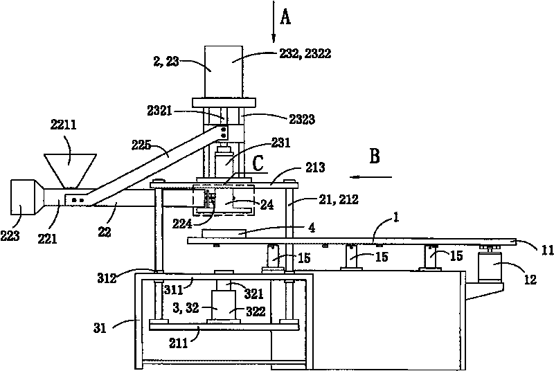
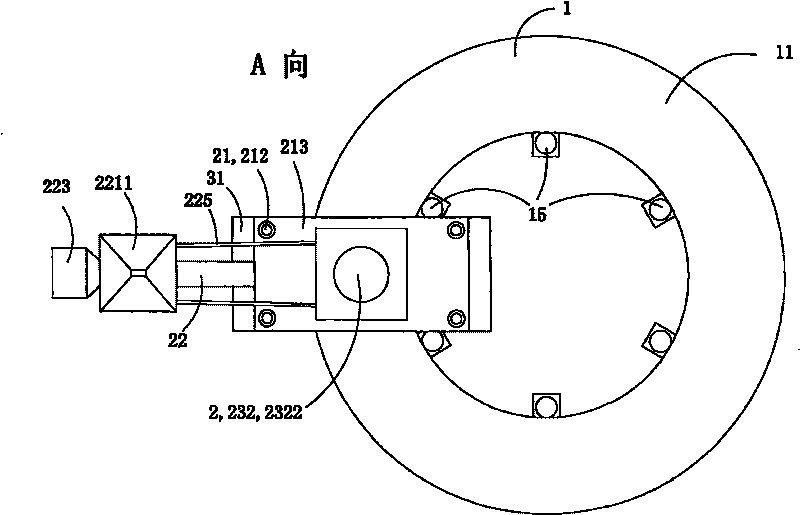
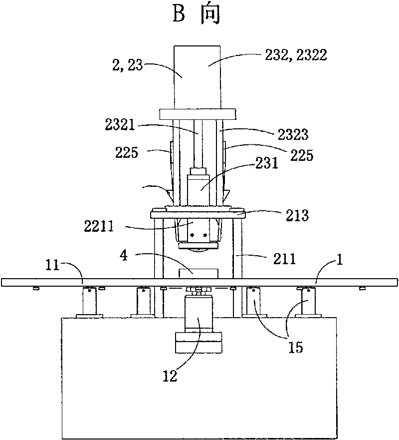
[0048] Figure 1 to Figure 8 A first embodiment of the invention is shown. in, figure 1 It is the first structure schematic diagram of the present invention; figure 2 yes figure 1 A-direction view; image 3 yes figure 1 B direction view; Figure 4 yes figure 1 Partial enlarged schematic diagram at C; Figure 5 yes Figure 4 cutaway diagram of Figure 6 yes figure 1 Schematic diagram of the cross-sectional structure of the middle injection nozzle arranged in the injection port of the injection head; Figure 7 yes Figure 5 Schematic diagram of the cross-sectional structure of the middle injection port; Figure 8 yes Figure 5 Schematic diagram of the cross-sectional structure of the middle injection nozzle.

[0049] See Figure 1 to Figure 3 , this embodiment is a single-color horizontal disc plastic injection molding machine, including a turntable device 1, an injection device 2 and a mold clamping device 3; Feet 15 and the driving device 12 that drives the ro...

Embodiment 2

[0064] Figure 9 to Figure 14 A second embodiment of the invention is shown, Figure 9 is a schematic diagram of the second structure of the present invention; Figure 10 yes Figure 9 Partial cross-sectional view at D; Figure 11 yes Figure 9 Schematic diagram of the cross-sectional structure of the Zhongguan feed nozzle set at the feed port of the injection head; Figure 12 yes Figure 11 Sectional view of the middle feed port; Figure 13 yes Figure 12 View from E direction; Figure 14 yes Figure 11 Schematic diagram of the structure of the Zhongguan material nozzle; Figure 15 yes Figure 14 F direction view.

[0065] This implementation is basically the same as Embodiment 1, the difference is:

[0066] See Figure 9 The turntable device 1 also has a pressure-bearing tray 13 for supporting the disc 11 when the injection head is pressed against the mold and is fixedly arranged relative to the clamping frame 31. In non-injection molding, that is, when the inje...

Embodiment 3

[0071] Figure 16 It is a schematic cross-sectional structural diagram of the connection between the pre-molding mechanism and the injection head through the injection connector in the third structure of the present invention, showing the third embodiment of the present invention.

[0072] This embodiment is basically the same as Embodiment 1, the difference is that: the shape of the discharge connection part 2242 of the feeding coupling 224 is a conical tenon with a protruding conical surface, and the feed of the injection head The shape of the connecting portion 244 is a frustum-shaped groove with an inner concave tapered surface matching the shape of the discharge connecting portion 2242 of the feeding coupling.


PUM

PropertyMeasurementUnit
surfaceaaaaaaaaaa

Abstract

The present invention discloses a horizontal disc-type plastic injection molding machine, comprising a turntable device, an injecting device and a die closing device. The turntable device consists of a rotary disc and a driving unit which drives the disc to rotate; the injecting device comprises an injecting stand, a horizontal pre-plasticizing mechanism , a vertical pre-plasticizing mechanism and an injecting head which are arranged on the injecting stand; the die closing device comprises a die closing stand and a die closing cylinder which is arranged on the die closing stand beneath the disc; the piston of the die closing cylinder which can move up and down, is fixedly connected to the injecting head through the injecting stand to drive the injecting head to move up and down. The invention can shorten the journey of the piston of the die closing cylinder and shorten the time on the journey, thus production efficiency is effectively improved.

Description

technical field [0001] The invention belongs to a plastic injection molding machine, in particular to a disc type plastic injection molding machine. Background technique [0002] Disc-type plastic injection molding machine is a kind of equipment specially used for manufacturing plastic soles. The discs used are often equipped with multiple sole molds of the same style and different sizes at the same time. Therefore, it is necessary to set the molds on the turntable for plastic injection. The molding machine injects and molds the molds with the same style and different code numbers in stages, and facilitates the mold opening and taking out the molded soles. [0003] Disc plastic injection molding machines are generally divided into horizontal plastic injection molding machines and vertical plastic injection molding machines due to the different selection of pre-molding mechanisms. Horizontal plastic injection molding machines have pre-molding mechanisms set in the horizontal ...

Claims


Application Information

Patent Timeline
Patent Type & Authority Patents(China)
IPC IPC(8): B29C45/07B29C45/64B29C45/06B29C45/54B29C45/20B29C45/23B29C45/17
Inventor 金孝禹
Owner 金孝禹
Why Eureka
Try Eureka