Vacuum cleaner
A technology for vacuum cleaners and vacuum cleaners, applied in the direction of vacuum cleaners, suction filters, cleaning equipment, etc., which can solve the problems of inconvenient work of cleaning dust or cleaning dust buckets, and achieve the effects of light weight, convenient cleaning, and simple structure
- Summary
- Abstract
- Description
- Claims
- Application Information
AI Technical Summary
Problems solved by technology
Method used
Image

Examples
Embodiment Construction
[0037] In the following, the vacuum cleaner of the present invention will be described in detail in conjunction with the accompanying drawings and embodiments: wherein the same parts and components as those in the prior art use the same names and symbols, and the detailed description thereof is omitted.
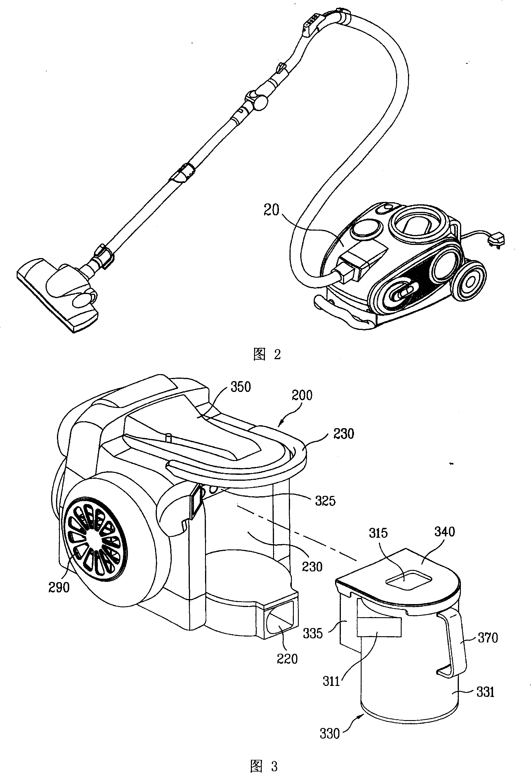
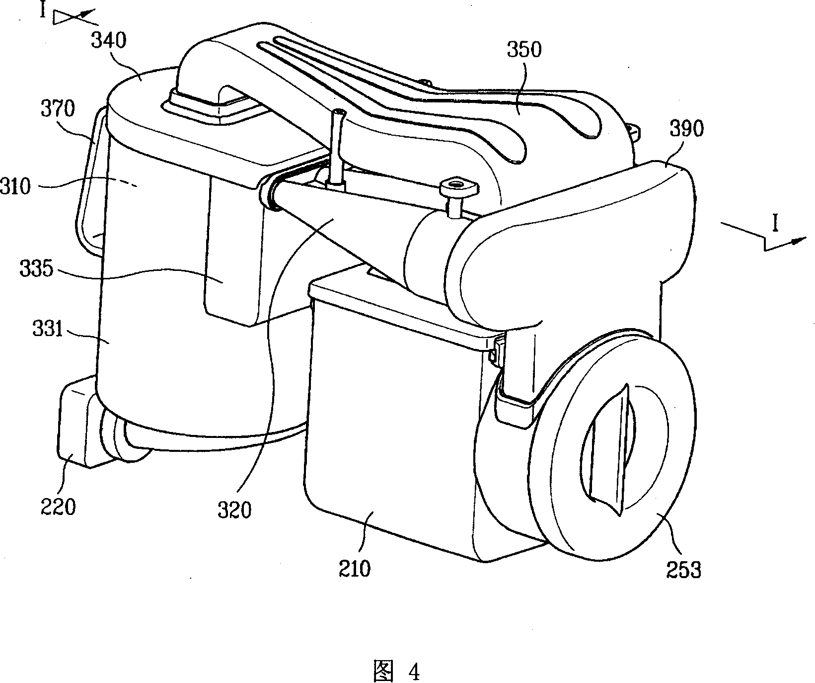
[0038] As shown in Figures 3-5, the present invention is a vacuum cleaner, mainly including a suction nozzle (not shown), a cleaner body 200, a drive unit 210, and dust collecting devices 310, 320, 330 for separating and storing dust.
[0039] The front lower end of the vacuum cleaner body 200 is provided with a body suction 220, and the body suction port 220 communicates with the suction nozzle, and allows the air containing dust to flow in. One side surface of the cleaner body 200 is provided with a body discharge part 290, and the body discharge part 290 discharges the air from which the dust is separated by the dust collecting device.
[0040] The driving unit 210 is prov...
PUM
 Abstract
Description
Claims
Application Information