Steam inlet valve of a steam turbine

A steam inlet valve, steam turbine technology, applied in the direction of lift valve, valve detail, valve device, etc.

Inactive Publication Date: 2008-01-23
ALSTOM TECH LTD
View PDF0 Cites 1 Cited by
  • Summary
  • Abstract
  • Description
  • Claims
  • Application Information

AI Technical Summary

Problems solved by technology

[0003] However, especially in modern construction types of steam turbines that are required to operate at ever-increasing temperatures, even this cladding can approach its load limit

Method used


Image

  • Steam inlet valve of a steam turbine
  • Steam inlet valve of a steam turbine
  • Steam inlet valve of a steam turbine

Examples


Embodiment Construction

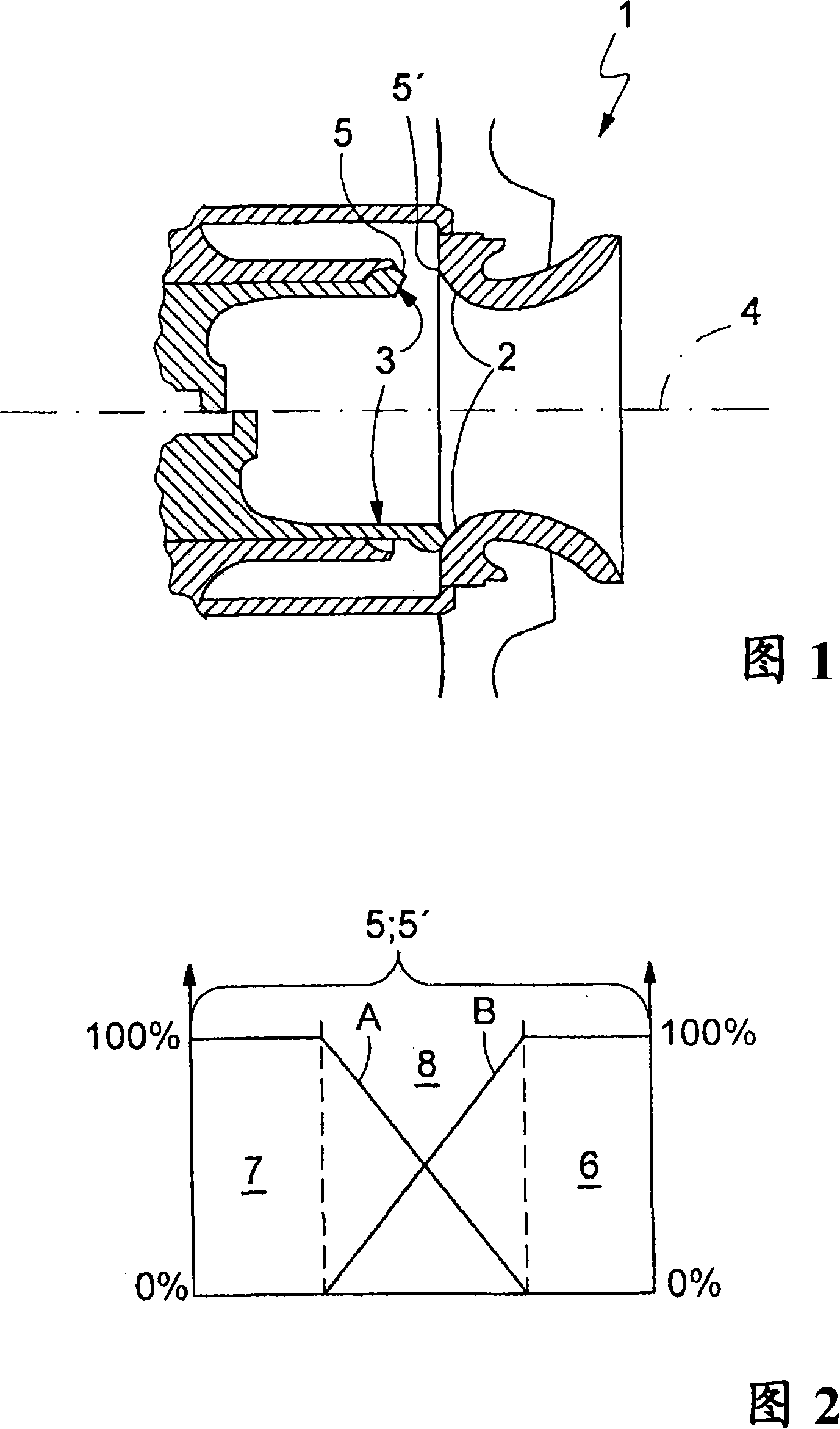
[0030] As shown in FIG. 1, according to the present invention, a steam turbine inlet valve 1, which is not shown, has a valve seat 2 and an associated valve body 3. In this way, the part of the inlet valve 1 above the dividing line 4 indicates an open state, and below the dividing line 4 is a closed state. When the inlet valve 1 is closed, the valve body 3 sealingly abuts on the contact area 5'of the valve seat 2 through the contact area 5. In this case, at least one of the two contact regions 5 or 5'is configured to be multi-layered, and has the configuration shown in FIG. 2 or FIG. 3, for example.

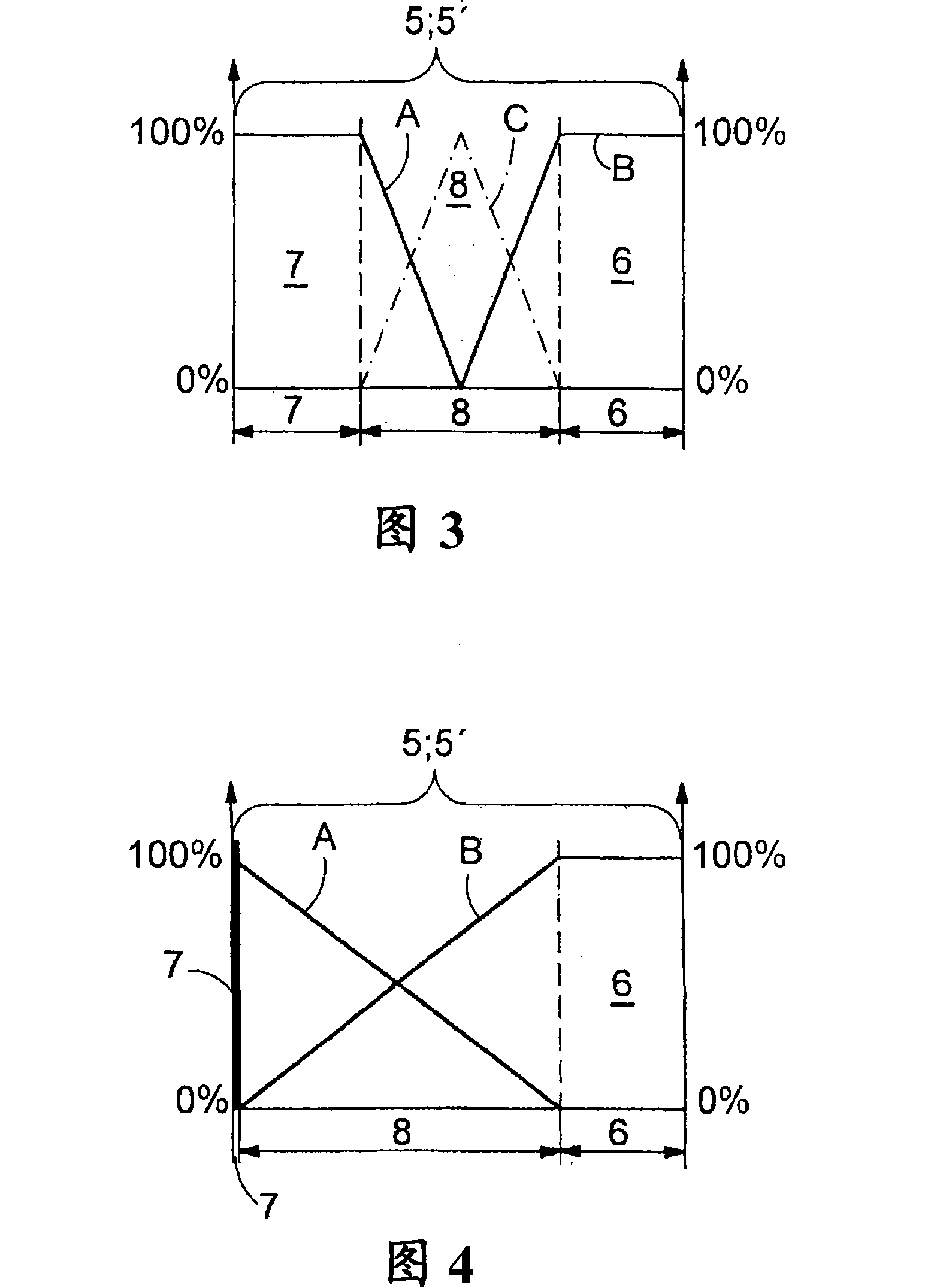
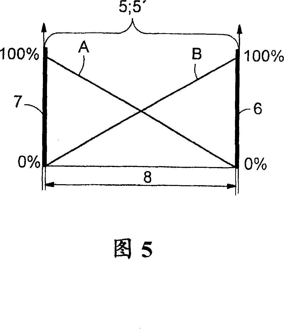
[0031] Figure 2 is a graphical depiction of the concentrations of materials A and B in the contact areas 5, 5'. In this case, in principle, the contact area 5, 5'according to FIG. 2 has at least one sealing area 6 facing the other contact area 5, 5', and a base area 7 facing away from this sealing area 6, And the transition area 8 between the sealing area 6 and the base area 7. The b...


PUM


Abstract

A steam inlet valve ( 1 ) of a steam turbine, with a valve seat ( 2 ) and a valve body ( 3 ) which, when the valve is closed, bears via a contact region ( 5 ) with sealing effect on a contact region ( 5' ) of the valve seat ( 2 ). At least one of the two contact regions ( 5, 5' ) has at least one sealing region ( 6 ) which faces the other contact region ( 5, 5' ), a base region ( 7 ) which faces away from the sealing region ( 6 ), and a transition region ( 8 ) which is situated between them, wherein the sealing region ( 6 ) is formed from a sealing material (B) and the base region ( 7 ) is formed from a base material (A), which the valve seat ( 2 ) or the valve body ( 3 ) also approximately comprises. In order to increase the wear resistance of the contact regions ( 5, 5' ) and of the steam inlet valve ( 1 ) as a result of it, the concentration of the base material (A) reduces from the base region ( 7 ) in the direction towards the sealing region ( 6 ) in the same way as the concentration of the sealing material (B) reduces from the sealing region ( 6 ) in the direction towards the base region ( 7 ), so that both materials (A, B) are to be found in the transition region ( 8 ).

Description

Technical field [0001] The invention relates to a steam turbine inlet valve with a valve seat and a valve body. Background technique [0002] Steam turbine inlet valves are usually subject to high stress and are subject to constant wear as a result. In particular, the high temperature of several hundred degrees Celsius encountered during the operation of the steam turbine will cause creep along with the mechanical load imposed on the steam inlet valve, which will damage the function of the steam inlet valve in the long run. Moreover, the high mechanical load during the sudden temporary closing of the inlet valve, various oxidation processes and the erosion caused by solid particles will all have the consequence of damaging the function of the inlet valve. In order to resist such wear, it is known that in the valve seat area and / or the valve body area that is sealed against the valve seat through the contact area when the valve is closed, a so-called stellite coating is provided. ...

Claims


Application Information

Patent Timeline
Patent Type & Authority Applications(China)
IPC IPC(8): F01D17/10
CPCF16K25/005F16K1/42F01D17/145
Inventor R·B·斯卡林
Owner ALSTOM TECH LTD
Why Eureka
Try Eureka