
Intelligent heat preserving and freezing protecting technology for heat exchanger

A heat exchanger and plate heat exchanger technology, applied in damage protection, lighting and heating equipment, refrigeration components, etc. The effect of preventing heat exchanger damage, preventing environmental low temperature and low power consumption

Inactive Publication Date: 2008-01-23
JIANGSU TENESUN ELECTRICAL APPLIANCE
View PDF0 Cites 6 Cited by
  • Summary
  • Abstract
  • Description
  • Claims
  • Application Information

AI Technical Summary

Problems solved by technology

There are two possibilities for freezing the unit: one is because the outdoor ambient temperature is very low in winter, and the temperature is lower than the freezing point of water. The water inside cannot be circulated, and the water is not discharged as required. After a long time, the water in the water system may freeze. Very narrow plate heat exchanger) is easy to be damaged by freezing, causing damage to the whole unit. Another reason is that when entering winter, the ambient air temperature is very low, usually below 7°C. When the air source heat pump is running, if the air The humidity is high, and the fins of the air heat exchanger may be frosted. For this, the equipment manufacturer usually defrosts the system through reverse control. Scaling or partial blockage occurs inside the water heating heat exchanger, and the water in some channels cannot circulate, especially when the water temperature is low, as the water temperature gradually drops, freezing may also occur, which will also freeze the heat exchanger , causing damage to the entire unit

Method used


Image

  • Intelligent heat preserving and freezing protecting technology for heat exchanger
  • Intelligent heat preserving and freezing protecting technology for heat exchanger

Examples


Embodiment Construction

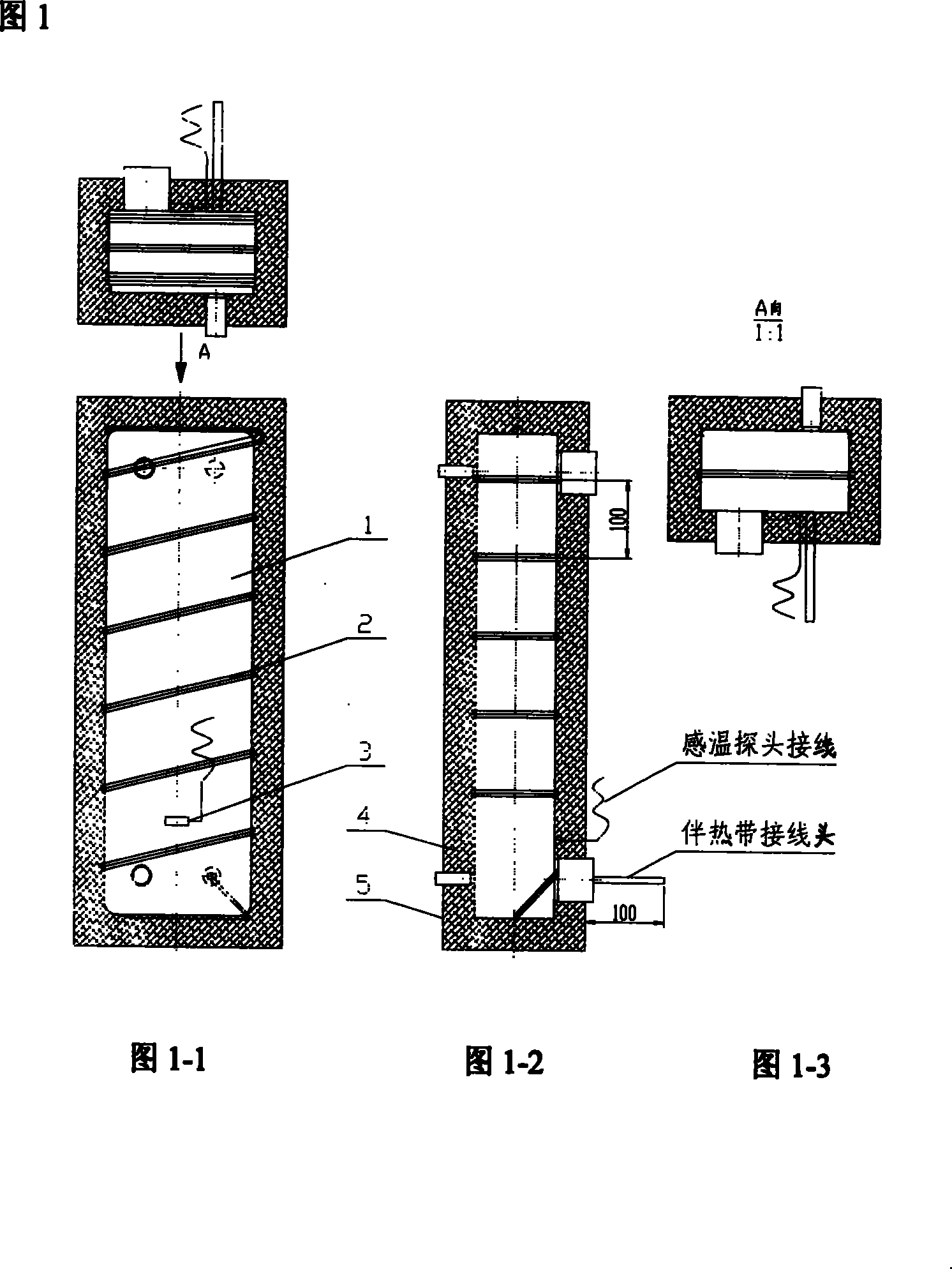
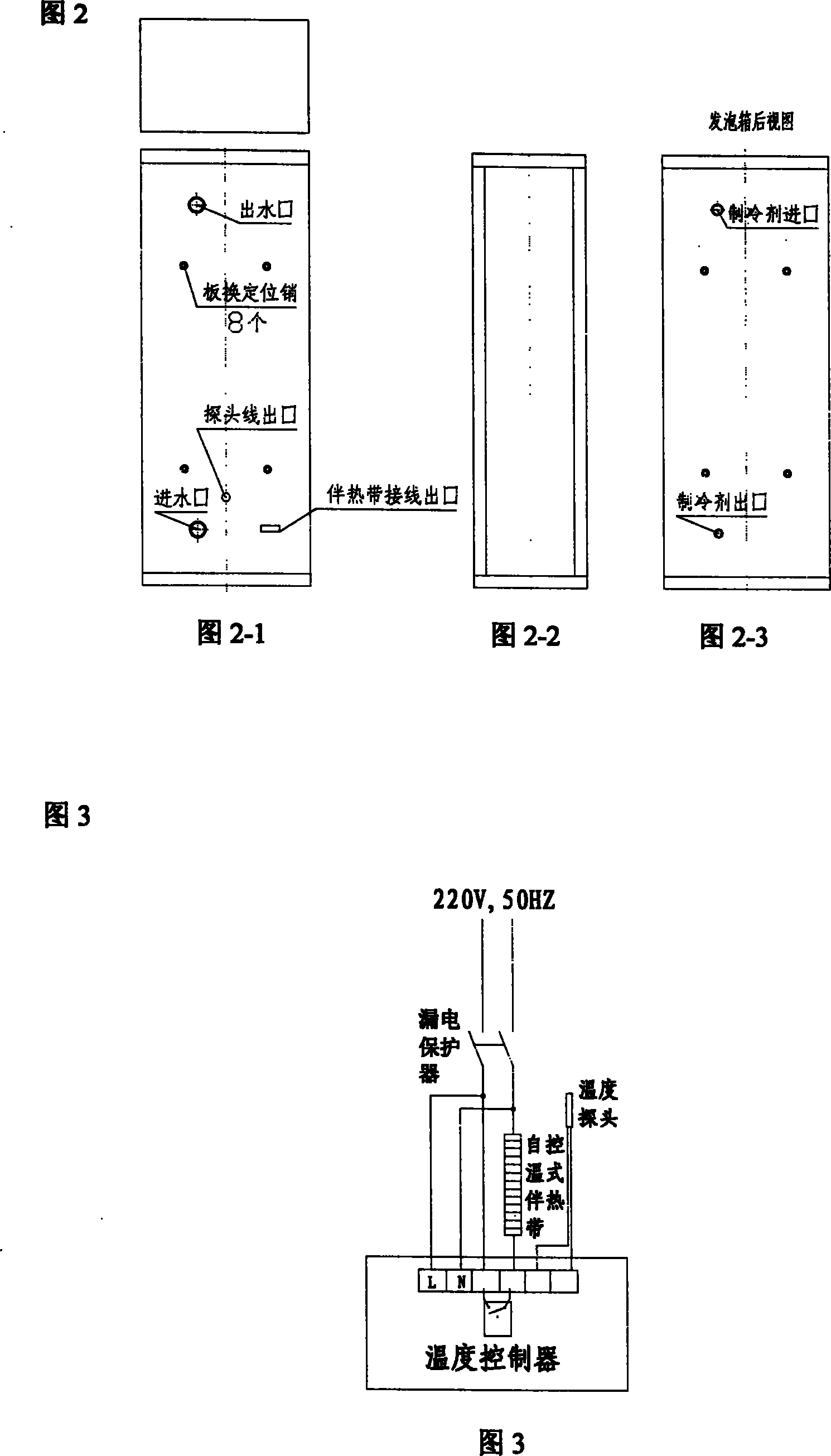
[0018] An embodiment of the present invention will be illustrated below in conjunction with Fig. 1-1 to Fig. 3, and will be described in detail so that those skilled in the art can more easily understand the features and functional characteristics of the present invention, rather than to limit the scope of the present invention.

[0019] According to the method of the present invention, the steps of the intelligent heat preservation and antifreeze implementation method for plate heat exchangers include:

[0020] a: Wind the heating cable (2) of the corresponding length obtained from the calculation and experimental results on the surface of the heat exchanger according to the calculated spacing of 100 mm, and stick the heating cable (2) to the surface of the heat exchanger (1) with adhesive tape;

[0021] b: Fix the temperature probe (3) at the middle and lower part of the surface of the heat exchanger (1);

[0022] c: The foam (4) on the surface of the heat exchanger (1) is 4...


PUM

PropertyMeasurementUnit
Lengthaaaaaaaaaa

Abstract

The invention provides an intelligent thermal-preservation and anti-freezing method for a heat exchanger, which comprises the following procedures: a heat-trace belt in a length got by calculation and experiment(s) is wound on the surface of the heat exchanger in calculated interval, and is adhered on the surface of the heat exchanger by an adhesive tape; a temperature probe is fixed at the middle lower part of the surface of the heat exchanger; 40mm-thick polyurethane is formed on the surface of the heat exchanger, the heat-trace belt and the temperature probe are foamed integrally with the heat exchanger so that they are heat preserved and heat isolated from outside, and the external joints of the heat-trace belt and the temperature probe are reserved; when the temperature probe for the surface of the heat exchanger detects that the temperature is lower than the specified temperature, the temperature control will start the heat trace to carry out temperature compensation; when the probe detects that the temperature is higher than another specified temperature, the temperature control will stop the heat trace. The invention has the advantages of the small footprint, the capability for preventing low environmental temperature, the capability for preventing damage due to freezing caused by temperature drop in the pipeline or joints of the heat exchanger, and the energy saving, etc.

Description

technical field [0001] The invention relates to a heat preservation and antifreeze method for a heat exchanger, more specifically a method for providing intelligent heat preservation and antifreeze for a heat exchanger by using a self-controlling heating cable. Background technique [0002] The existing air heat source pump hot water units on the market have the phenomenon of cold damage in winter. There are two possibilities for freezing the unit: one is because the outdoor ambient temperature in winter is very low, and the temperature is lower than the freezing point of water. The water inside cannot be circulated, and the water is not discharged as required. After a long time, the water in the water system may freeze. Very narrow plate heat exchanger) is easy to be damaged by freezing, resulting in damage to the entire unit. Another reason is that when entering winter, the ambient air temperature is very low, usually below 7°C. When the air source heat pump is running, i...

Claims


Application Information

Patent Timeline
IPC IPC(8): F25B47/00
Inventor 王天舒刘树堂王玉军顾小刚
Owner JIANGSU TENESUN ELECTRICAL APPLIANCE
Learn More