Device for testing and analyzing warehouse separated type denitrated catalyzer

A denitration catalyst, testing and analysis technology, which is applied in the field of SCR denitration catalyst sampling, analysis and detection devices in power plants, can solve the problems of poor comparability of test results, long interval time, long time consumption, etc., and achieves the effect of saving analysis and testing time and increasing comparability.

Active Publication Date: 2008-01-23
CPI YUANDA ENVIRONMENTAL PROTECTION ENG +1
View PDF0 Cites 12 Cited by
  • Summary
  • Abstract
  • Description
  • Claims
  • Application Information

AI Technical Summary

Problems solved by technology

[0003] At present, only when the boiler is shut down, the catalyst for denitrification is taken out from the catalyst layer in the boiler and returned to the catalyst manufacturer or sent to the laboratory for analysis to observe the mechanical strength, service life and poisoning of the catalyst. According to the activity test, pressure drop loss, mechanical Strength, poisoning resistance, service life and flue gas adaptability to make a comprehensive evaluation of the time interval is long, and it is inconvenient to replace, so there is no timely judgment on the poisoning situation and cause of the denitrification catalyst, especially for th

Method used


Image

  • Device for testing and analyzing warehouse separated type denitrated catalyzer
  • Device for testing and analyzing warehouse separated type denitrated catalyzer
  • Device for testing and analyzing warehouse separated type denitrated catalyzer

Examples


Embodiment 1

[0034] Below in conjunction with accompanying drawing and embodiment the present invention will be further described:

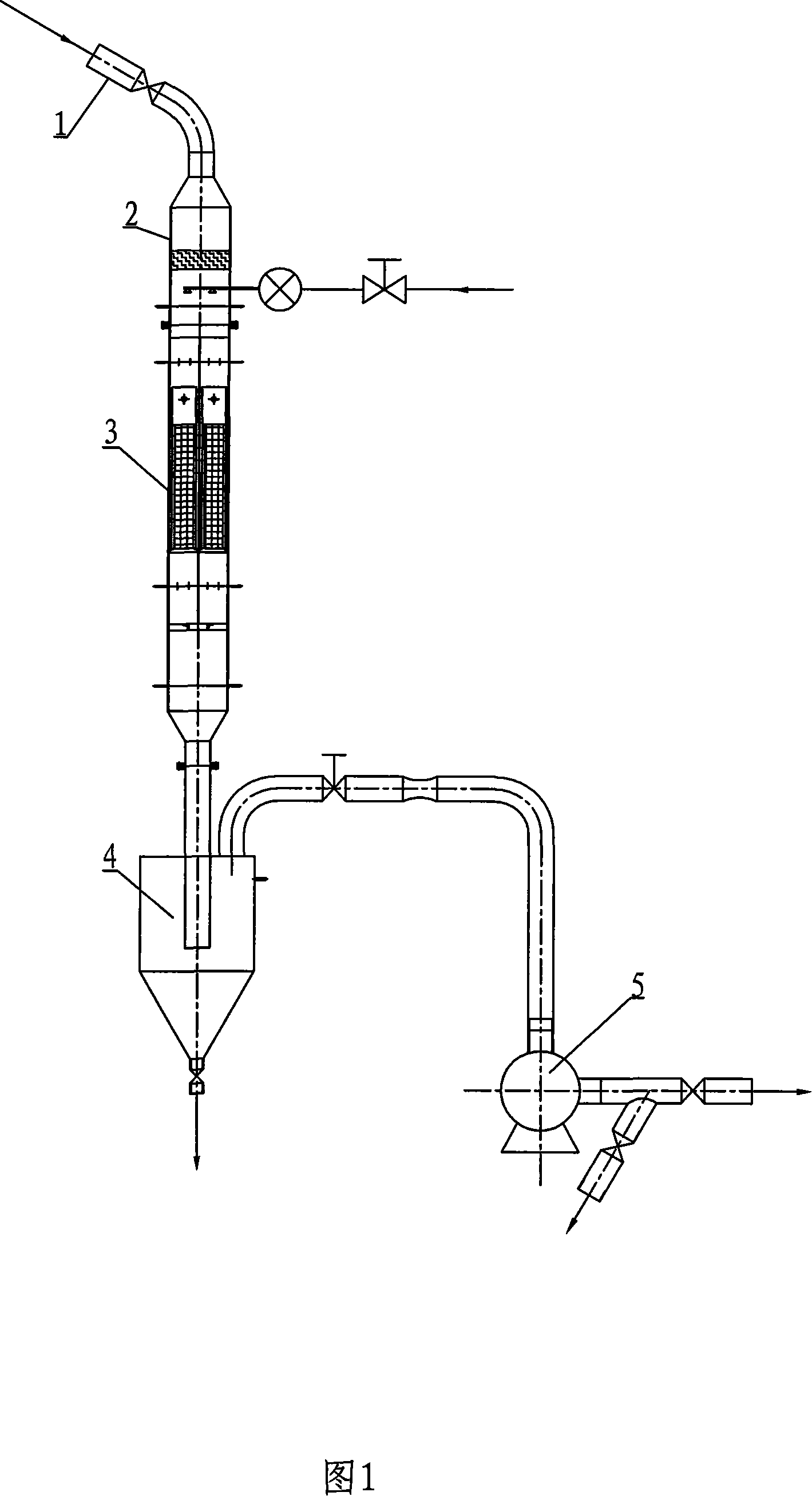
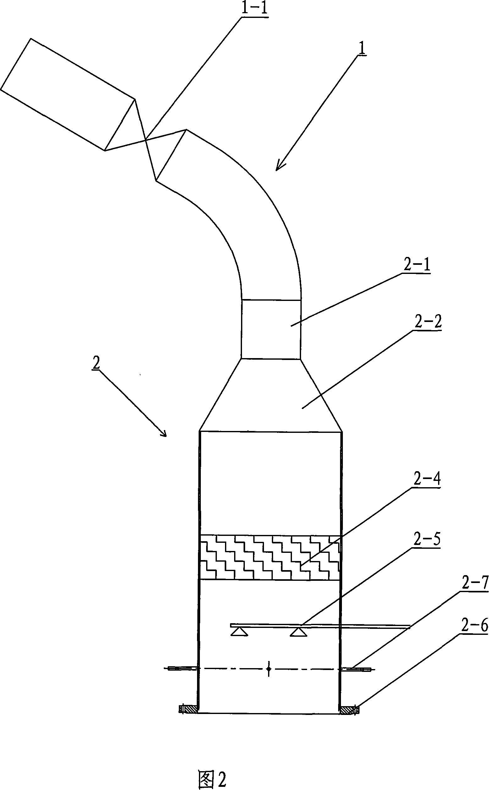
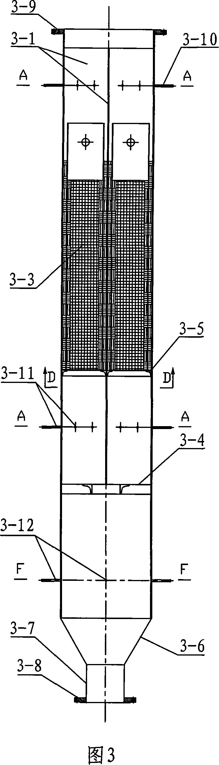
[0035] Please refer to Fig. 1, Fig. 2, Fig. 3, Fig. 4, and Fig. 5. The denitrification catalyst test and analysis device with compartments consists of a flue gas introduction pipe 1, a flue gas mixing component 2, an air induction device 5, and a flue gas purification component 4. A sub-compartment test reactor 3 is arranged between the flue gas mixing component 2 connected with the flue gas introduction pipe 1 and the flue gas purification component 4 connected with the air induction device 5, and the sub-compartment test reactor 3 mixes the flue gas The component 2 communicates with the flue gas purification component 4, and the inner cavity of the sub-compartment test reactor 3 is divided into four cavities 3-2 by the sub-compartment plate 3-1, and a Catalyst basket 3-3, put sub-chamber plate 3-1 in sub-chamber type test reactor 3 through sub-chamber plate s...

Embodiment 2

[0043] Please refer to Fig. 4, Fig. 5, Fig. 6, Fig. 7, Fig. 8, Fig. 9, and Fig. 10. For power plants without SCR reactors, the candidate catalysts are compared. The nozzle 2-1 of the ammonia gas metering injection system extends into the upper end of the flue gas mixing assembly 2, and a static mixer 3-9 is welded under the support frame of the compartment plate in the sub-chamber test reactor 3. The static mixer The downstream pressure measurement and sampling port 3-10 is set up below, and the flue gas is drawn from a suitable temperature range between the economizer and the air preheater. When the temperature is too high or too low, exceeding the operating range of the catalyst module, shut down the reaction test system.

[0044] In the absence of an SCR denitration reactor, ammonia gas needs to be sprayed in order for the denitration reaction to occur in the denitration catalyst module. The amount of ammonia injection needs to be adjusted and controlled according to the d...


PUM


Abstract

The invention discloses a split testing and analyzing device for a denitration catalyst. A split testing reactor (3) communicates a smoke mixing assembly (2) and a smoke cleaning assembly (4); the inner cavity of the split testing reactor (3) are divided into four cavities (3-2) by partition boards (3-1); in the middle of each cavity (3-2), a catalyst basket (3-3) is placed; the catalyst basket (3-3) comprises a main pipe and a sieve mesh; on the catalyst basket (3-3), a hanging hole is provided; between the upper and the lower opening of the cavity (3-2) and the catalyst basket, a sampling port is provided for measuring temperature and pressure for each cavity (3-2). The invention can concurrently carry out performance comparison and test on denitration catalysts of different specifications and types under the same smoke conditions, saves greatly the analysis and test time, and increases the comparability.

Description

technical field [0001] The invention relates to a sampling, analysis and detection device for a SCR denitration catalyst in a power plant, in particular to a bin-type denitration catalyst testing and analysis device capable of comparing the performance of catalysts of different types and specifications under the same flue gas condition. Background technique [0002] The denitrification catalyst is the core of SCR denitrification in power plants, and its performance has a decisive influence on the performance of the denitrification project. Unreasonable selection of catalyst will not only cause the denitration rate and other indicators of denitrification to fail to reach the guaranteed value, but also cause blockage of the catalyst and increase in pressure drop, resulting in boiler operation failure. In addition, if the catalyst is not selected properly, it may also cause catalyst poisoning , Accelerated wear and aging, the expected service life cannot be reached, and the cat...

Claims


Application Information

Patent Timeline
IPC IPC(8): G01N33/00G01N31/10G01N1/22
Inventor 李锋杜云贵罗小渝刘清才彭期耀尹正明廖帆隋建才杨剑王方群洪燕许川
Owner CPI YUANDA ENVIRONMENTAL PROTECTION ENG
Why Eureka
Try Eureka