Method for testing and analyzing warehouse separated type denitrated catalyzer

A denitration catalyst, testing and analysis technology, which is applied in the field of testing and analysis of sub-silo type denitration catalysts, can solve the problems of poor comparability of test results and long time consumption, and achieves the effect of saving analysis and testing time and increasing comparability.

Active Publication Date: 2008-01-23
CPI YUANDA ENVIRONMENTAL PROTECTION ENG +1
View PDF0 Cites 9 Cited by
  • Summary
  • Abstract
  • Description
  • Claims
  • Application Information

AI Technical Summary

Problems solved by technology

Therefore, when the current test methods of denitrification catalyst manufacturers compare various catalysts, not only need multiple tests, but also take a long time. The test and comparison of the suitability and good conditions of denitrification catalysts, and the environment in which each catalyst is located due to changes in various parameters of boiler exhaust flue gas, resulting in poor comparability of test results

Method used


Image

  • Method for testing and analyzing warehouse separated type denitrated catalyzer
  • Method for testing and analyzing warehouse separated type denitrated catalyzer
  • Method for testing and analyzing warehouse separated type denitrated catalyzer

Examples


Embodiment 1

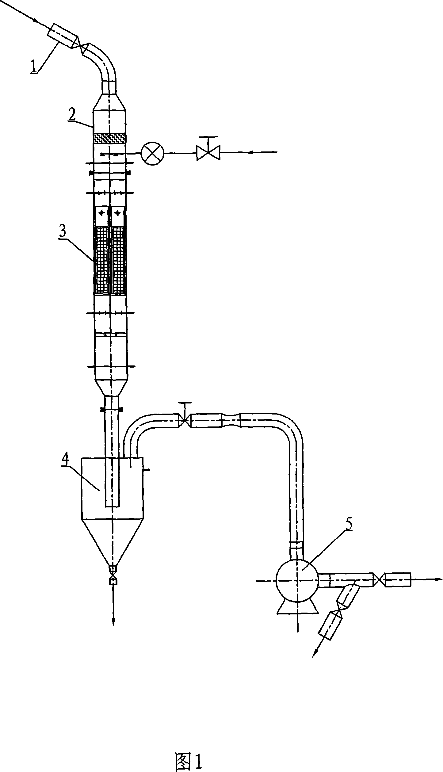
[0033] Please refer to Figure 1, Figure 2, Figure 3, Figure 4, and Figure 5. Example 1 is a method for testing and analyzing the compartmentalized denitrification catalyst for comparing candidate catalysts in Power Plant A with SCR reactors, including the following steps:

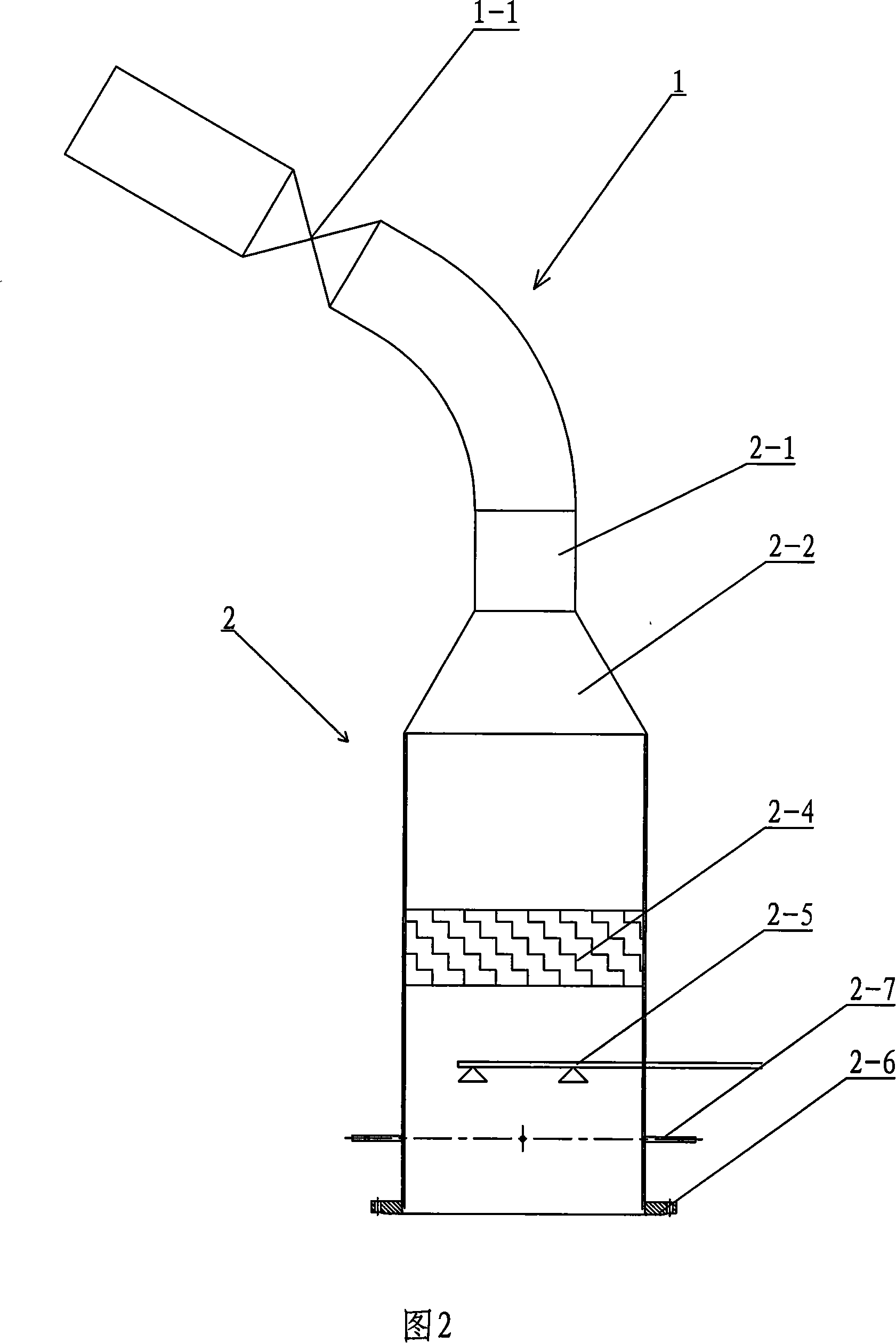
[0034] Step 1, system connection: a flue gas outlet pipe 1 is arranged downstream of the fly ash rectifier of the SCR reactor, and a cut-off valve 1-1 is arranged on the outlet pipe. Connect the flue gas outlet pipe 1, the flue gas mixing assembly 2, the sub-chamber test reactor 3, the flue gas outlet purification device 4, and the air induction device 5 into a whole, and the flue gas return pipes 5-6 in the air induction device Returning to the SCR reactor from above the air preheater, a shut-off valve 5-7 is set on the flue gas return pipe 5-6. The flue gas mixing assembly 2 contains a static mixer 2-4, a compressed air injection system 2-5 and an upstream total temperature and pressure measurement sampl...

Embodiment 2

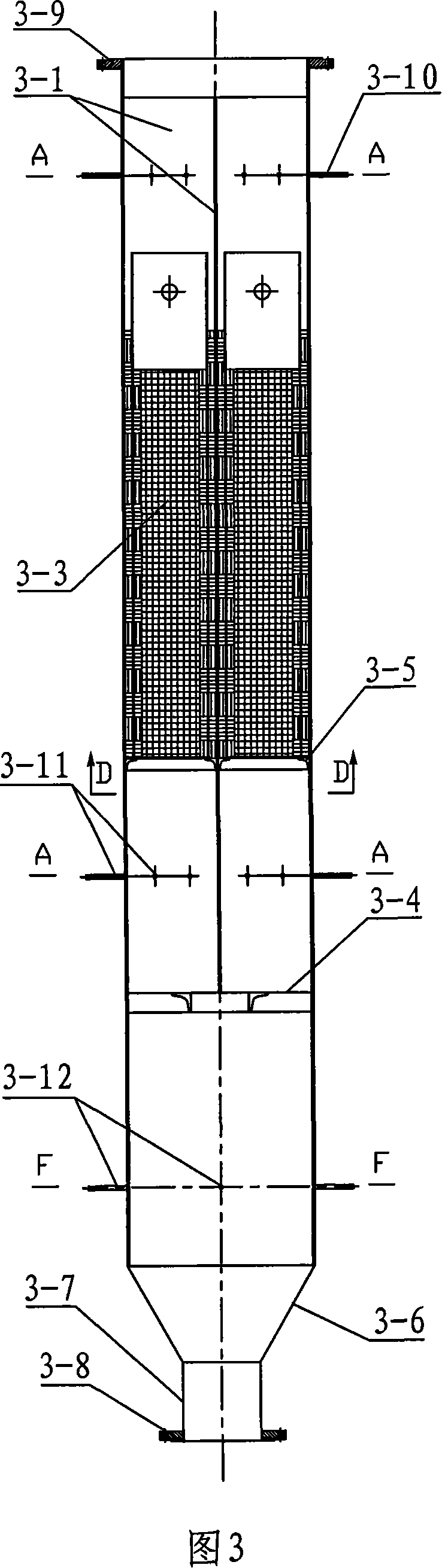
[0049] Please refer to Figure 4, Figure 5, Figure 6, Figure 7, Figure 8, Figure 9, Figure 10. For power plant B without SCR reactor, compare the candidate catalysts, take an appropriate amount of flue gas from the appropriate temperature range between the economizer and the air preheater, introduce the flue gas from the flue gas introduction pipe 1, and test and analyze the denitrification catalyst in separate bins The method is different from Example 1 in that the nozzle 2-1 of the ammonia gas metering injection system extends into the upper end of the flue gas mixing assembly 2, and the sub-compartment test reactor 3 is located under the support frame of the sub-compartment plate and welded with a static mixer. 3-9. In the absence of an SCR denitration reactor, ammonia gas needs to be sprayed in order for the denitration reaction to occur in the denitration catalyst module. The injection amount of ammonia needs to be adjusted and controlled according to the NO concentration...


PUM

PropertyMeasurementUnit
lengthaaaaaaaaaa

Abstract

The invention discloses a split testing and analyzing device for a denitration catalyst, which comprises the following procedures: 1. setting the split testing reactor (3); 2. loading catalyst; 3. connecting smoke and testing; 4. taking out catalysts for testing; in this way comprehensive evaluation can be carried out on catalysts, so as to get the most suitable catalyst. The invention can concurrently carry out performance comparison and test on denitration catalysts of different specifications and types under the same smoke conditions, can compare a plurality of catalysts, saves greatly the analysis and test time, and increases the comparability. The invention can not only be used for selecting the best catalyst for a built power plant of a SCR denitration project, but also be used for comparing a plurality of catalysts for the power plant of a to-be-built SCR denitration project, and for optimizing the alternative catalysts in a denitration catalyst producer.

Description

technical field [0001] The invention relates to a method for sampling, analyzing and detecting an SCR denitrification catalyst in a power plant, in particular to a bin-type denitrification catalyst test and analysis method capable of comparing the performance of catalysts of different types and specifications under the same flue gas condition. Background technique [0002] The denitrification catalyst is the core of SCR denitrification in power plants, and its performance has a decisive influence on the performance of the denitrification project. Unreasonable selection of catalyst will not only cause the denitration rate and other indicators of denitrification to fail to reach the guaranteed value, but also cause blockage of the catalyst and increase in pressure drop, resulting in boiler operation failure. In addition, if the catalyst is not selected properly, it may also cause catalyst poisoning , Accelerated wear and aging, the expected service life cannot be reached, and ...

Claims


Application Information

Patent Timeline
Patent Type & Authority Applications(China)
IPC IPC(8): G01N33/00G01N31/10G01N1/22
Inventor 杜云贵李锋罗小渝刘艺刘清才彭期耀尹正明隋建才廖帆王方群洪燕蒙剑
Owner CPI YUANDA ENVIRONMENTAL PROTECTION ENG
Why Eureka
Try Eureka