
Sensor for use in a plastics processing machine and method for operating such a sensor

A technology of sensors and processing machines, which is applied to register/instruct the work of machines, instruments, time registers, etc., and can solve the problems of lack of large-scale application, hindering computing work, and large computing workload of control devices.

Active Publication Date: 2008-01-23
KRAUSSMAFFEI TECH GMBH
View PDF3 Cites 18 Cited by
  • Summary
  • Abstract
  • Description
  • Claims
  • Application Information

AI Technical Summary

Problems solved by technology

[0005] However, in this way, the computational workload of the control device is very large, which hinders other computational work required for machine control in terms of operation
The large number of sensors in the control unit and the matching machine-specific algorithms are also quite costly, so this application has not been implemented on a large scale so far

Method used


Image

  • Sensor for use in a plastics processing machine and method for operating such a sensor

Examples


Embodiment Construction

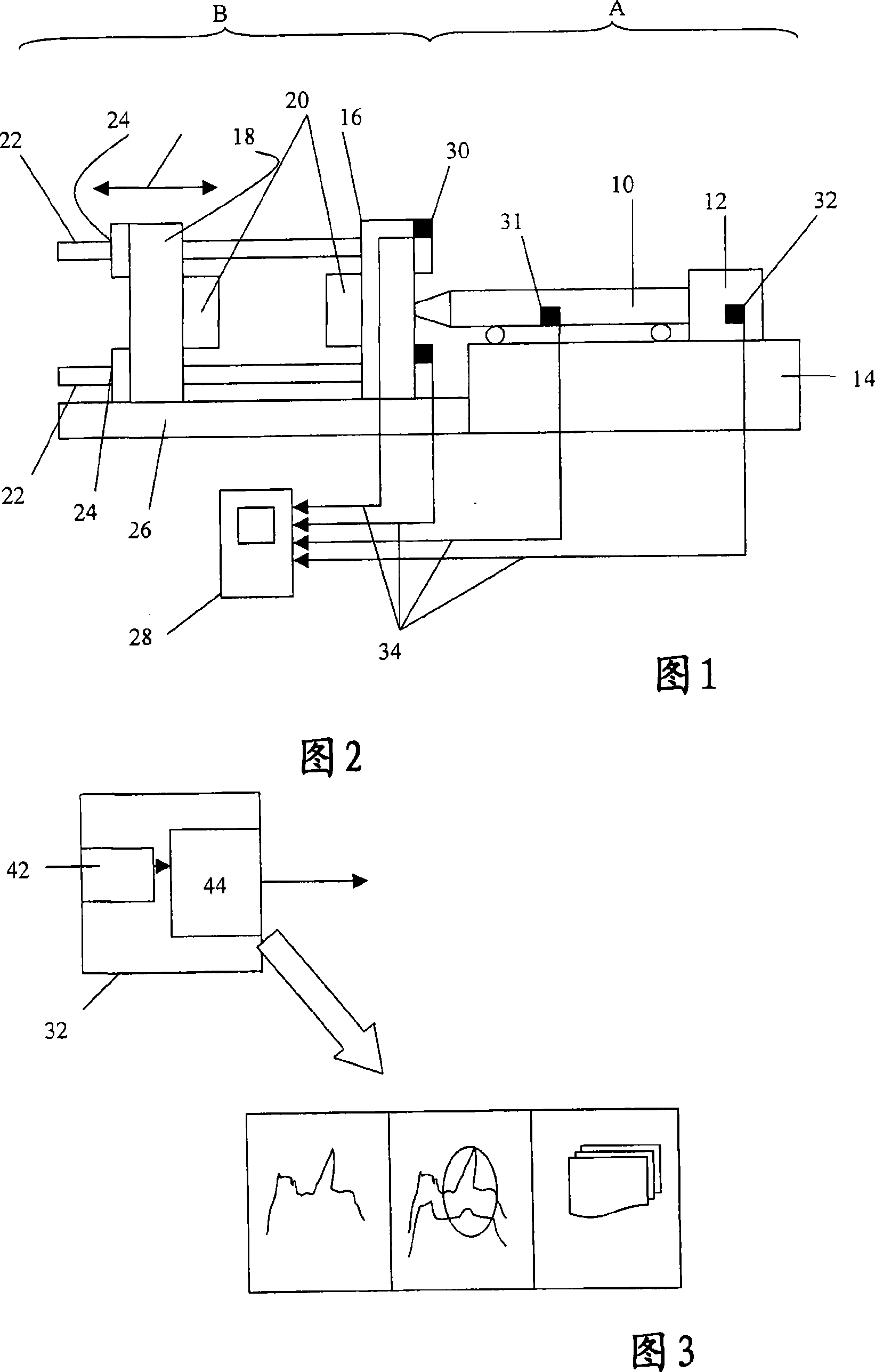
[0023] FIG. 1 shows a schematic view of an injection molding machine with a plasticizing unit and a clamping unit, which are arranged in areas A (plasticizing unit) and B (closing unit). The plasticizing unit in area A comprises a plasticizing cylinder 10 mounted reciprocally on a bed 14 and comprising an electric drive 12 at its end. The clamping unit in area B has, in a known manner, two platens, namely a fixed platen 16 and a movable platen 18 , to which a mold half 20 is fastened in each case. The formwork 18 is traversed by four beams 22 , of which only two are visible in FIG. 1 . The movable formwork 18 can be fixed relative to the crossbeam 22 by means of locking elements 24, so that in the closed state of the clamping unit a clamping pressure can be applied with hydraulic pressure pads mounted on the stationary formwork. Sensors 30 , 31 and 32 are fastened on the two pressure pads and on the plasticizing cylinder 10 as well as on the electric drive 12 .

[0024] A se...


PUM


Abstract

Sensor (32) for injection molding machines or extruders comprises a probe (42) and an integral processing unit (44). The processing unit categorizes the signals it receives from the probe by comparison with a classification table and sends an error signal to a control unit if a defect is detected. An independent claim is included for: a method for operating a sensor, as described.

Description

technical field [0001] The invention relates to a sensor for a machine for processing plastics and a method for its operation according to the preamble of claim 1 . Background technique [0002] The invention is particularly concerned with elements for identifying abnormal states of components or machine parts in plastics processing machines, which states reflect malfunctions, wear or maintenance necessity. [0003] In recent years the detection of unusual operating states in machines, which reflect defective machine parts or foreseen malfunctions, has been carried out in various technical fields. It is also increasingly desirable to be able to understand, in particular, maintenance and maintenance work before actual functional failures occur. Avoiding damage that has not yet occurred by replacing potentially failing parts during normal maintenance intervals is always far more beneficial than having to accept considerable unplanned downtime in the event of an unanticipated ...

Claims


Application Information

Patent Timeline
IPC IPC(8): G07C3/14B29C45/76B29C47/92B29C48/92
CPCB29C2945/76006G01D1/14B29C2947/92295B29C2947/924G07C3/14G07C3/00B29C2945/76341B29C2947/92457B29C45/768B29C2947/92504B29C2947/92361B29C2947/92409B29C47/0009B29C2945/76939B29C2947/92047B29C2947/92019B29C2947/92209B29C2945/7604B29C2945/76163B29C2947/92057B29C48/03B29C48/92B29C2945/76177B29C2948/92019B29C2948/92047B29C2948/92057B29C2948/92209B29C2948/92295B29C2948/92361B29C2948/924B29C2948/92409B29C2948/92457B29C2948/92504
Inventor O·乌尔巴内克
Owner KRAUSSMAFFEI TECH GMBH
Learn More