Electrostatic chuck with heater

An electrostatic chuck and heater technology, which is applied in the manufacture of circuits, electrical components, semiconductors/solid-state devices, etc., can solve the problems of longer substrate processing time, lower substrate processing capacity, and deterioration of device yield, so as to improve heating efficiency , good heat uniformity, and high long-term reliability

Active Publication Date: 2008-01-23
NGK INSULATORS LTD
View PDF1 Cites 8 Cited by
  • Summary
  • Abstract
  • Description
  • Claims
  • Application Information

AI Technical Summary

Problems solved by technology

[0003] However, in the conventional electrostatic chuck with a heater described above, since the volume resistivity of the dielectric layer is small, the loading and unloading reactivity of the substrate placed on the substrate mounting surface may decrease.
If the loading and unloading reactivity decreases, the time for the substrate to be separated from the electrostatic chuck becomes longer, so the processing time of the substrate becomes longer, and the processing capacity of the substrate per unit time decreases
Furthermore, since the main component of the above-mentioned resistance heating element is niobium (Nb), there is a possibility that the niobium component diffuses in the support member on which the resistance heating element is installed.
Due to the diffusion of this niobium component, the resistance value of the resistance heating element as a whole increases, and the heat generation density of the diffused part differs from the desired design value.
In addition, since the degree of diffusion is not uniform in each part of the substrate, the temperature distribution on the substrate mounting surface becomes large, and as a result, there may be a problem that the heat uniformity of the substrate decreases.
If the thermal uniformity of the substrate is lowered, it will be difficult to achieve uniform etching or film formation in the semiconductor manufacturing process, and as a result, the yield of the manufactured device may deteriorate

Method used


Image

  • Electrostatic chuck with heater
  • Electrostatic chuck with heater

Examples


Embodiment Construction

[0014] Embodiments of the present invention will be described below.

[0015] The electrostatic chuck will be described.

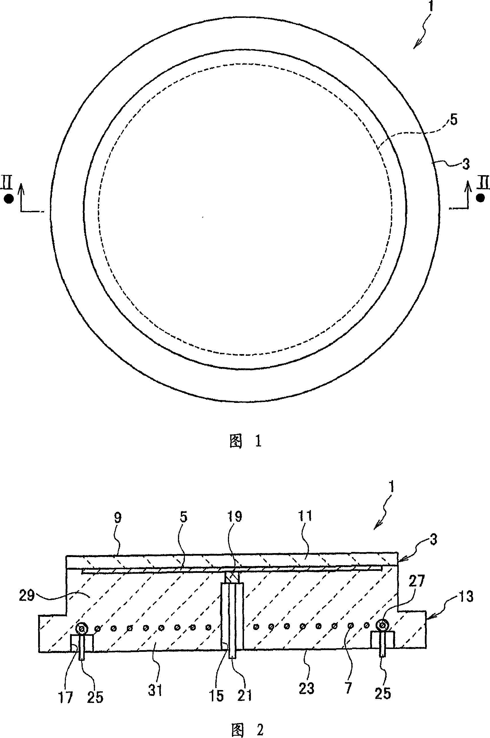
[0016] 1 is a plan view showing an electrostatic chuck with a heater according to an embodiment of the present invention, and FIG. 2 is a cross-sectional view taken along line II-II of FIG. 1 .

[0017] As shown in FIGS. 1 and 2 , an electrostatic chuck with a heater 1 according to an embodiment of the present invention includes: a base body 3 made of a sintered body containing alumina; an electrode 5 embedded in the upper side of the base body 3 ; and The resistance heating element 7 is embedded in the lower side of the base body 3 .

[0018] Describe the base.

[0019] As shown in FIGS. 1 and 2 , the base 3 is formed in a disk shape, and the upper surface (surface) of the base 3 is formed as a substrate mounting surface 9 on which a substrate such as a wafer is mounted. Furthermore, a portion from the electrode 5 to the upper side in the base body 3 ,...


PUM

PropertyMeasurementUnit
thicknessaaaaaaaaaa
thicknessaaaaaaaaaa

Abstract

The present invention provides an electrostatic chuck with a heater, comprising: a base made of a sintered body containing alumina; an electrode provided on the upper side of the base; and a resistance heating element embedded in the lower side of the base, the above-mentioned The base includes a dielectric layer from the electrodes to the upper surface of the base and a support member from the electrodes to the lower surface of the base. This electrostatic chuck with heater is characterized in that the carbon content in the dielectric layer is 100 ppm or less, the carbon content in the support member is 0.03 to 0.25 wt %, and the resistance heating element is formed in a coil shape and its main component is niobium. .

Description

technical field [0001] The present invention relates to a coulomb type electrostatic chuck with a heater. Background technique [0002] Conventionally, a Coulomb type electrostatic chuck with a heater has been used in the manufacture of semiconductors and the like. A substrate made of ceramics is provided on this electrostatic chuck with a heater, and electrodes and a resistance heating element are provided inside the substrate. The upper surface of the base is formed as a substrate mounting surface on which a substrate such as a wafer is mounted. The portion of the base from the electrodes to the substrate mounting surface is formed as a dielectric layer, and the portion from the electrodes to the lower surface of the base is formed as a supporting member (for example, refer to Patent Document 1: Japanese Patent Application Laid-Open No. 11-12053). [0003] However, in the above conventional electrostatic chuck with a heater, since the volume resistivity of the dielectric...

Claims


Application Information

Patent Timeline
Patent Type & Authority Applications(China)
IPC IPC(8): H01L21/683
CPCH01L21/6831H01L21/68757H01L21/687
Inventor 曻和宏川尻哲也服部亮誉
Owner NGK INSULATORS LTD
Why Eureka
Try Eureka