
Flexible neon tube lamp

A neon tube light, flexible technology, applied in the direction of lampshade, lighting device, light source, etc., can solve the problems of not making full use of LED light, not achieving the neon light luminous effect, and low luminous brightness of the lamp body, avoiding bad products, light The effect of homogenizing and improving luminous brightness

Inactive Publication Date: 2008-01-30
姚志峰
View PDF3 Cites 14 Cited by
  • Summary
  • Abstract
  • Description
  • Claims
  • Application Information

AI Technical Summary

Problems solved by technology

[0002] Because neon lights have the advantages of continuous, uniform, and high luminous brightness, they are widely used as advertisements or decorations. However, neon lights use glass tubes, so they are subject to great restrictions during packaging and transportation, and are easily broken during transportation. Professionals must use professional tools for installation or maintenance, which is inconvenient
[0003] For this reason, an inventor has invented a patent application number: 200410032066.5 titled "A kind of Hose Lamp Improvement Structure". Set the distance between the lamp body to achieve the effect of neon lights. This technology claims to achieve the effect of neon lights, but it does not achieve the luminous effect of neon lights in the application; and the inventor invented a patent number: 200420046325.5 name The invention is "a flexible tube lamp with neon effect", which also discloses a method of uniforming the light emitted by the LED by arranging a milky white diffuser on the strip-shaped core body, and the core body passes through the outer layer of the fixed body Combined with astigmatism, but because the astigmatism between the core wire body and the outer fixed body is milky white and the thickness reaches 14-16mm, because the astigmatism is milky white and opaque, it has a certain blocking effect on light, and some light is blocked It is not irradiated inside. It is measured by optical instruments that when the light emitted by the LED passes through the milky white astigmatism with a thickness of 14mm, the light is 76.8% of that before passing through, so 33.2% is blocked. When passing through the milky white astigmatism with a thickness of 2mm The light behind the astigmatism will be weakened by 4.72%, so a structure with strong light transmission, uniform light, and atomized light is needed to replace the existing technology
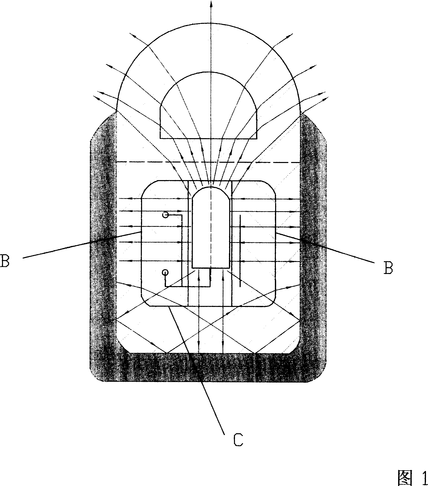
[0004] In addition to the low luminance of the lamp body due to the above reasons, there is also a low utilization rate of the light emitted by the LED, because about 70% of the light emitted by the LED will be used from the front end of the LED to the astigmatism body, and about 27% of the light emitted by the LED will be used. % of the light penetrates the core wire of the lamp body from the side of the LED and shines on both sides, and about 3% of the light penetrates the core wire of the lamp body from the bottom surface B of the LED and shines on the bottom surface C (as shown in Figure 1). Undoubtedly, this part of the light wasted without being used
[0005] Some inventors also invented a patent application number: 200520058121.2 titled "A Flexible Tube Lamp with Concentrating Effect". Although the invention improves the luminous effect of the light-emitting surface, since the astigmatism body is set as an opaque body in order to uniformly emit light, it blocks part of the light from refracting the light-emitting surface to a certain extent, and does not make full use of the light emitted by the LED. Therefore, there is also a need for a structure with strong light transmission, uniform light, and atomized light to replace the existing technical structure

Method used


Image

  • Flexible neon tube lamp
  • Flexible neon tube lamp
  • Flexible neon tube lamp

Examples


Embodiment Construction

[0039] The present invention will be further described below in conjunction with the drawings and specific embodiments.

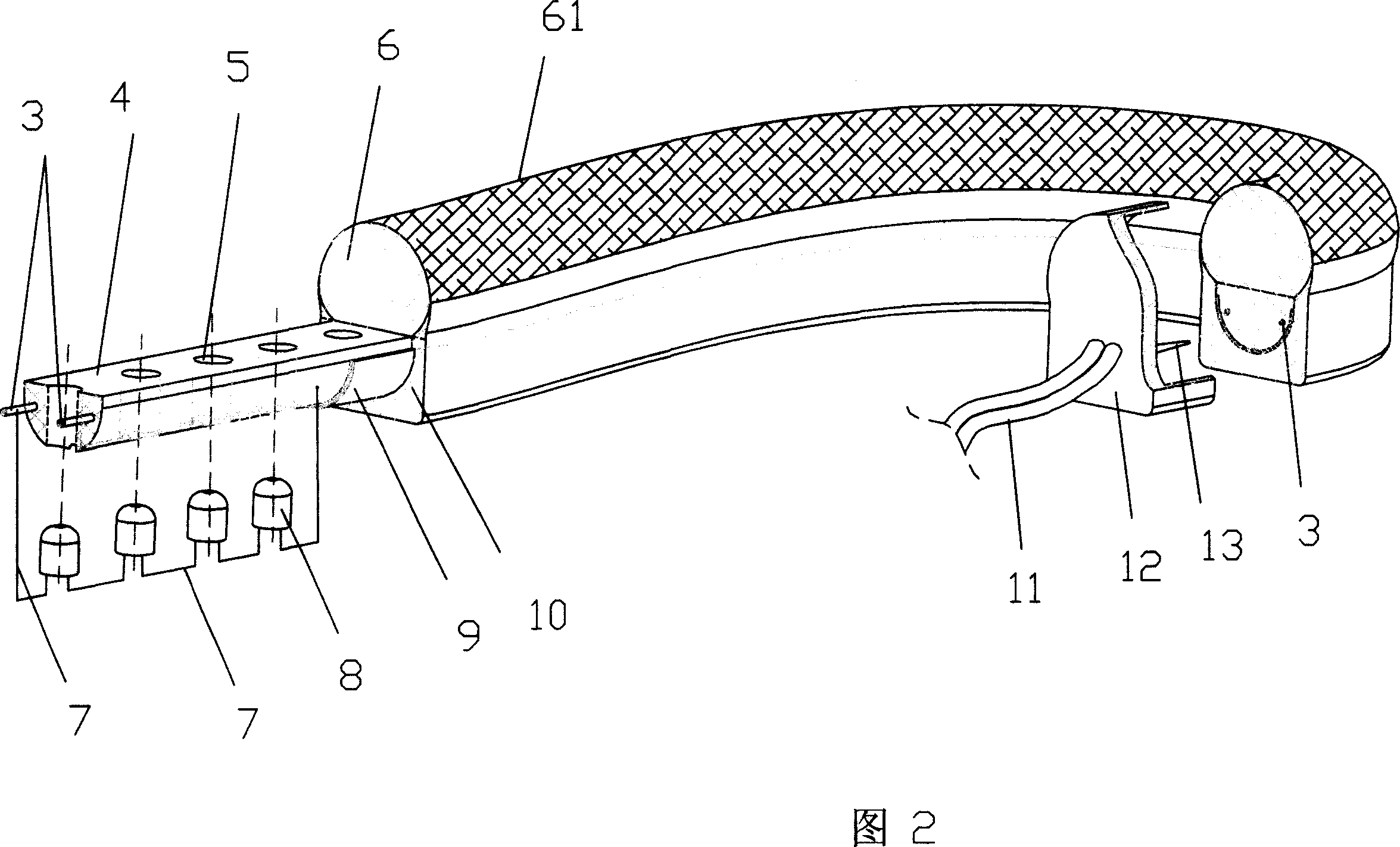
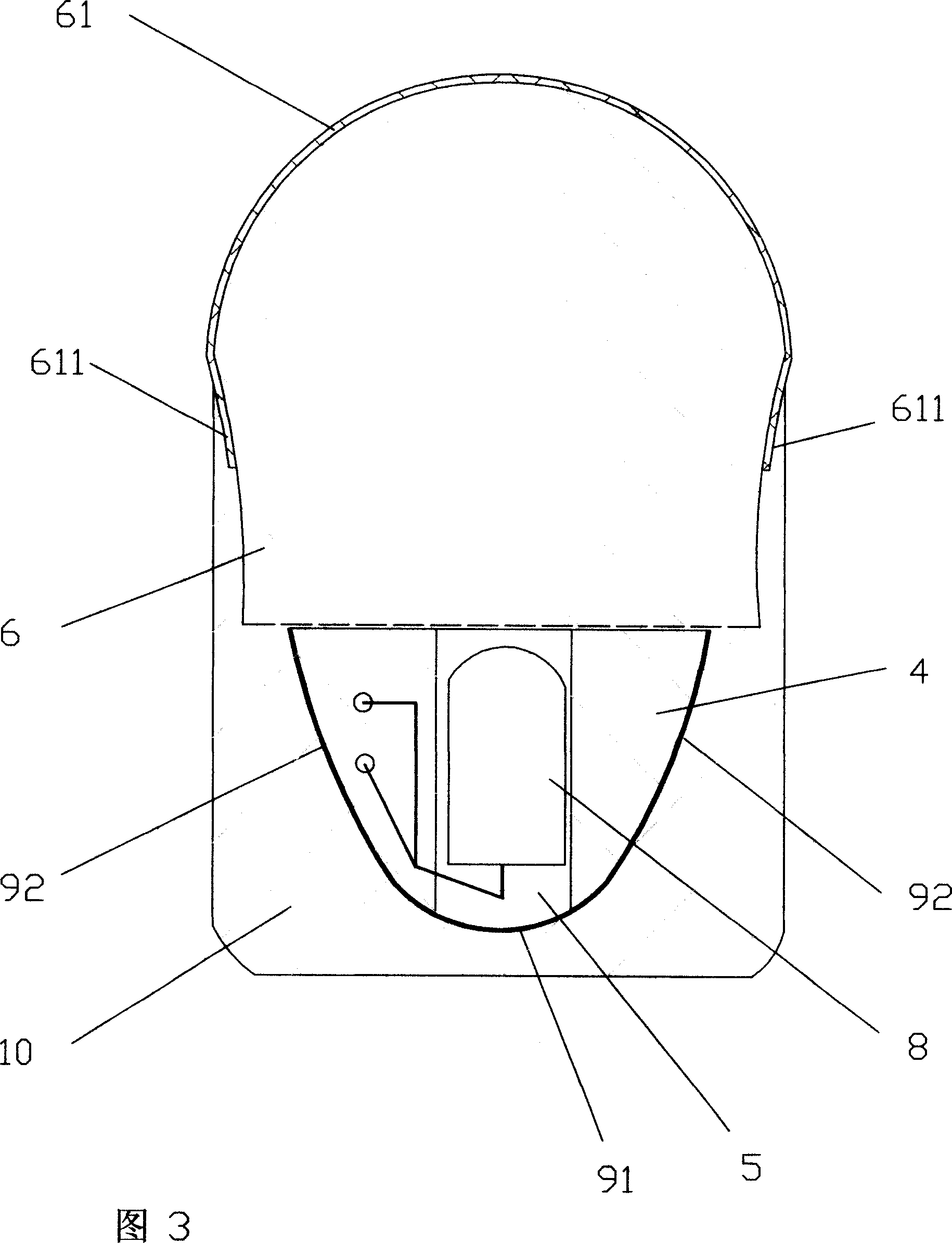
[0040]Referring to Figure 2, the present invention includes a flexible lamp body core wire 4, the flexible lamp body core wire is extruded and formed by flexible plastic, and a reflective layer with mirror effect is provided on both sides and bottom surface along the longitudinal direction of the lamp body core wire 4, The light-reflecting layers provided on both sides and bottom of the core wire 4 of the lamp body constitute a concave mirror 9 with a light-gathering effect in the transverse direction of the core wire 4, and at least two of them can be connected to the power supply or signal control along the longitudinal direction in the core wire 4 The wire 3 for electrical connection of the device is provided with a lamp body hole 5 for accommodating the luminous body in the core wire 4, and the lamp body core wire 4 is made of a flexible plastic material. T...


PUM


Abstract

The invention discloses a soft neon lamp strip, comprising a core line of a soft lamp body extruded from soft plastic, a reflecting layer with mirror effect arranged along two side surfaces and a bottom surface of the vertical direction of the core line of the lamp body. At least two wires that can electrically connected with the power or a signal controller and a lamp body hole are arranged along the vertical direction of the core line of the lamp body a transparent soft reflecting layer is arranged on the top of the core line of the soft lamp body along the vertical direction of the core line of the lamp body, the surface of the transparent soft reflecting layer is provided with a foggy layer, and the foggy layer is a frosted layer of the surface of the transparent soft reflecting layer, or a translucent film with foggy effect which can be a color coating or paint with foggy effect that coated on the surface of the transparent soft reflecting layer, and the thickness of the translucent film is 0.01 mm to 0.8mm. Therefore the invention has the advantages of equal lighting, high light availability and brightness, and low cost.

Description

Technical field [0001] The invention relates to a lighting device, in particular to a flexible neon tube lamp. Background technique [0002] Because neon lights have the advantages of continuous, uniform, and high luminous brightness, they are widely used as advertisements or as decorations. However, neon lights use glass tubes, so they are greatly restricted during packaging and transportation, and they are easily broken during transportation. Professionals must use professional tools to operate the installation or maintenance, which causes many inconveniences. [0003] To this end, an inventor invented a patent application number: 200410032066.5 titled "an improved structure for a hose lamp". This invention discloses a kind of (as shown in Figure 1) hope to set the shape of the milky white PVC refractive layer and pass Set the distance between the lamp bodies to achieve the neon effect of the tube light. This technology claims to achieve the neon effect, but it can not achieve ...

Claims


Application Information

Patent Timeline
IPC IPC(8): F21S4/00F21V3/04F21V23/00F21Y101/02
CPCF21V13/04F21S4/007F21Y2101/02F21S4/26F21Y2115/10
Inventor 姚志峰
Owner 姚志峰
Learn More