Structure unit of heating installation

A technology for structural units and heating equipment, applied in lighting and heating equipment, climate sustainability, hot water central heating systems, etc., can solve the problems of limited matching between plastic and hydraulic requirements, and achieve the effect of easy replacement

Inactive Publication Date: 2008-01-30
GRUNDFOS MANAGEMENT AS
View PDF1 Cites 8 Cited by
  • Summary
  • Abstract
  • Description
  • Claims
  • Application Information

AI Technical Summary

Problems solved by technology

[0004] This highly integrated structural unit has proven to be very good in practice, but has certain drawbacks, namely that the plastics used are only matched to the hydraulic requirements to a very limited degree

Method used


Image

  • Structure unit of heating installation
  • Structure unit of heating installation
  • Structure unit of heating installation

Examples


Embodiment Construction

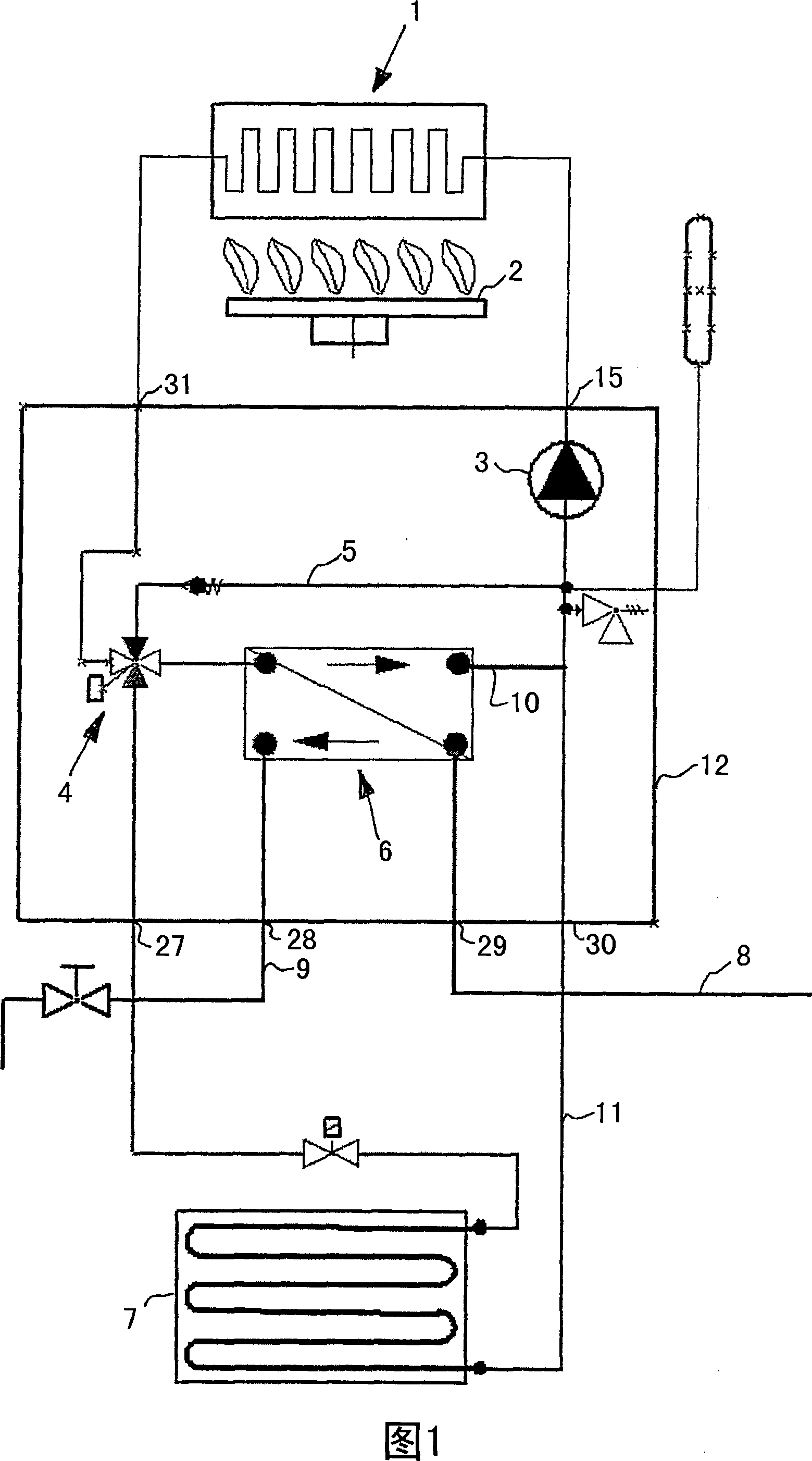
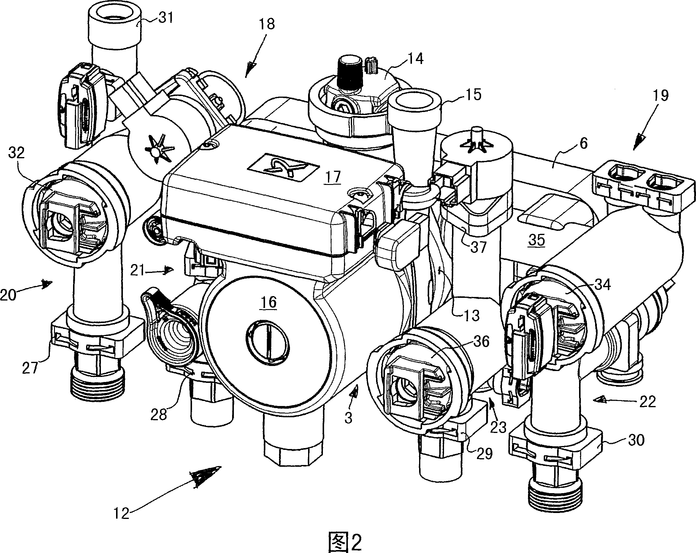
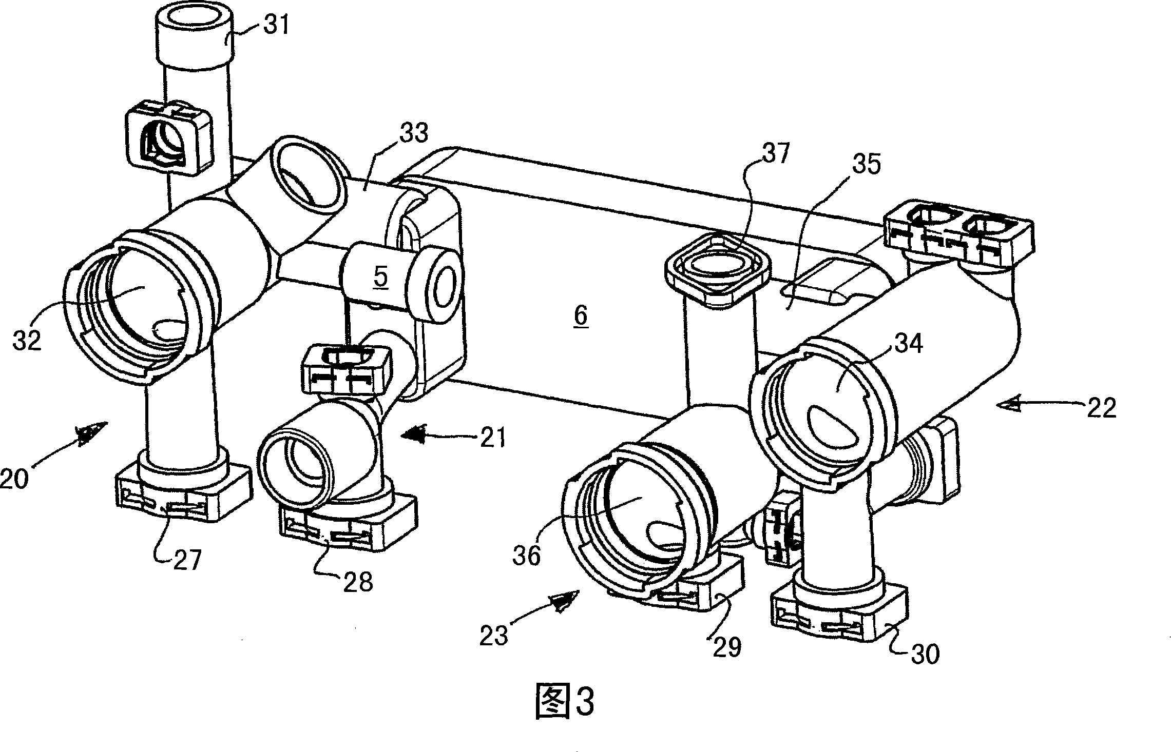
[0040]The heating installation shown in FIG. 1 has a first heating circuit in which circulating water is heated by means of a main heat exchanger 1 with burners 2 . The water flows through the main heat exchanger 1 by means of the circulation pump 3 and is then sent to the 3 / 3 (three-position three-way) reversing valve 4 from which the water is selectively sent to the A connected overflow pipe 5, or a heat exchanger 6 in the form of a fin heat exchanger, or a cooling body 7 for indoor heating. The water can flow back to the circulation pump 3 and thus to the main heat exchanger 1 in a short distance via the overflow pipe 5 . This switching position is used to quickly heat the water circulated there. In the second switching position, the water heated in the main heat exchanger 1 is fed to the plate heat exchanger 6, in which the process water is heated countercurrently, the process water comes from the process water pipe 8 and is heated It leaves the heat exchanger 6 through ...


PUM


Abstract

The structural unit (12) has two heating circuits that are provided for space heating and hot water generation, respectively, and housing components (20-23) that are made from plastic e.g. polyphenylene sulphide. A plate heat exchanger (6) is provided for domestic water heating, where the housing components form a conduit for the heat exchanger. The housing components are connected with one another based on connection pairs by using a snap-on connection, where one of the housing components comprises an insertion housing.

Description

technical field [0001] The invention relates to a structural unit of a heating system comprising two heating circuits having the features stated in the preamble of claim 1 . Background technique [0002] Such structural units already belong to the prior art and are generally used for so-called gas radiators, which are provided as wall-mounted, but can also be floor-mounted. This compact device has a main heat exchanger in which the circulating water is heated and fed either to a heating circuit provided for room heating or to a generally plate heat exchanger The heat exchanger is used to heat the industrial water through the plate heat exchanger. The structural unit here generally comprises a plurality of housing components made of plastic, at least one pump set (Pumpenaggregat), a heat exchanger for heating the industrial water, and all other possible electrical, mechanical and / or hydraulic parts, as long as they can be reasonably combined in the structural unit. These c...

Claims


Application Information

Patent Timeline
Patent Type & Authority Applications(China)
IPC IPC(8): F24D3/08F24D3/10F24D19/00
CPCF24H9/14F24H9/142Y02B30/108F24H1/52
Inventor 奥拉夫·延森
Owner GRUNDFOS MANAGEMENT AS
Why Eureka
Try Eureka