Image checking apparatus

A technology for inspection devices and graphics, applied in measuring devices, image enhancement, image analysis, etc., can solve the problems of difficult design, lower resolution, high lens price, etc., and achieve the effect of preventing the increase of device cost and high resolution

Inactive Publication Date: 2008-01-30
USHIO DENKI KK
View PDF3 Cites 12 Cited by
  • Summary
  • Abstract
  • Description
  • Claims
  • Application Information

AI Technical Summary

Problems solved by technology

[0016] However, it is generally used to design the same optical characteristics for different wavelengths of light, which is more difficult than the design of an optical system for imaging light of a

Method used


Image

  • Image checking apparatus
  • Image checking apparatus
  • Image checking apparatus

Examples


Embodiment Construction

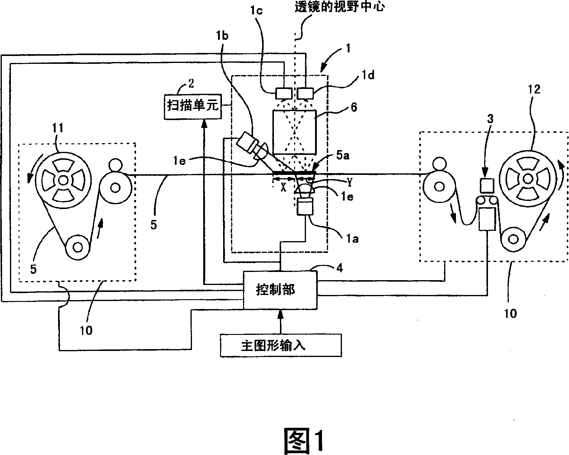
[0038] Fig. 1 is a block diagram of a wiring pattern inspection device according to a first embodiment of the present invention. In addition, in any of the embodiments shown below, the case where the substrate is a TAB tape will be described, but the present invention can be applied to pattern inspection of various substrates capable of transmitted illumination other than the TAB tape. For example, a silicon wafer can transmit infrared rays. If infrared rays are used for reflected illumination light and transmitted illumination light, the same inspection can be performed on the above-mentioned wiring pattern formed on the silicon wafer.

[0039] The graphic inspection apparatus of the present embodiment, as shown in Figure 1, possesses: tape conveying mechanism 10, is made up of sending out reel 11 and take-up reel 12 by conveying TAB tape 5; The tape 5 irradiates transmitted illumination light and reflected illumination light, and images the pattern 5a; the scanning unit 2 sc...


PUM


Abstract

The present invention provides a pattern checking device which can get the two sides of transmitted illuminating picture and reflected illuminating picture with scanning the camera unit and lighting unit once and the resolution is not reduced. When the checking pattern (5a) of the TAB strip (5) is fetched, the scanning is executed by that the transmitted illuminating unit (1a) and the reflected illuminating unit (1b) irradiate respectively transmission illuminating light and reflected illuminating light and the checking pattern (5a) wholly passes through the checking part (1) by the scanning unit (2). Thereby the transmitted illuminating picture and the reflected illuminating picture of the checking pattern (5a) are read and stored to the control part (4). The control part (4) compares the stored transmitted picture with the reference pattern used for transmission illuminating, checks whether the wiring pattern of the transmitted illuminating picture is in the scope of the fixed dimension relative to the reference pattern, namely checks whether a ''wide part'' or a ''thin part'' exists in the wiring pattern and judges whether the checking pattern (5a) is excellent.

Description

technical field [0001] The present invention relates to a pattern inspection device, in particular to a wiring pattern inspection device for illuminating a wiring pattern formed on a substrate such as a TAB (Tape Automated Bonding) tape by reflective lighting and transmitted lighting, And compare the reflected illumination image and the transmitted illumination image, so as to judge whether it is good or not. Background technique [0002] In the inspection of wiring patterns, as a method and device for distinguishing dust (foreign matter) adhering to the surface or back of the substrate from defects in wiring patterns and preventing erroneous detection, for example, Patent Document 1, Patent Document 2 and Patent Document 3 etc. were proposed. [0003] The above publication describes comparing an reflected illumination image obtained by developing reflected illumination light on a substrate on which a wiring pattern is formed, and a transmitted illumination image obtained b...

Claims


Application Information

Patent Timeline
IPC IPC(8): G01N21/956G01R31/28H01L21/66
CPCG01N21/88G01N21/956G01N21/95684G01N2021/95638G06T2207/30141G06T7/70H05K3/0002
Inventor 林宏树松田僚三
Owner USHIO DENKI KK
Why Eureka
Try Eureka