
Continuously alternating closed and open loop power control

一种闭环功率控制、开环功率的技术,应用在放大的控制、传输的控制/均衡、功率管理等方向,能够解决开环传输功率不确定、功率阶跃不确定、功率阶跃超过等问题

Active Publication Date: 2008-01-30
TELEFON AB LM ERICSSON (PUBL)
View PDF0 Cites 11 Cited by
  • Summary
  • Abstract
  • Description
  • Claims
  • Application Information

AI Technical Summary

Problems solved by technology

However, since the open-loop transmission power is relatively uncertain before switching to closed-loop, the power step (step) generated when switching from open-loop power control to closed-loop power control will also be relatively uncertain, which may cause produce discontinuity
In addition, since the gain control signal during closed-loop power control can be significantly different from the gain control signal generated after switching from closed-loop power control to open-loop power control, there may also be inconsistencies when switching from closed-loop power control to open-loop power control. continuous
These discontinuities can cause power steps between adjacent slots to exceed the relative transmit power requirements during transitions between open-loop and closed-loop power control

Method used


Image

  • Continuously alternating closed and open loop power control
  • Continuously alternating closed and open loop power control
  • Continuously alternating closed and open loop power control

Examples


Embodiment approach

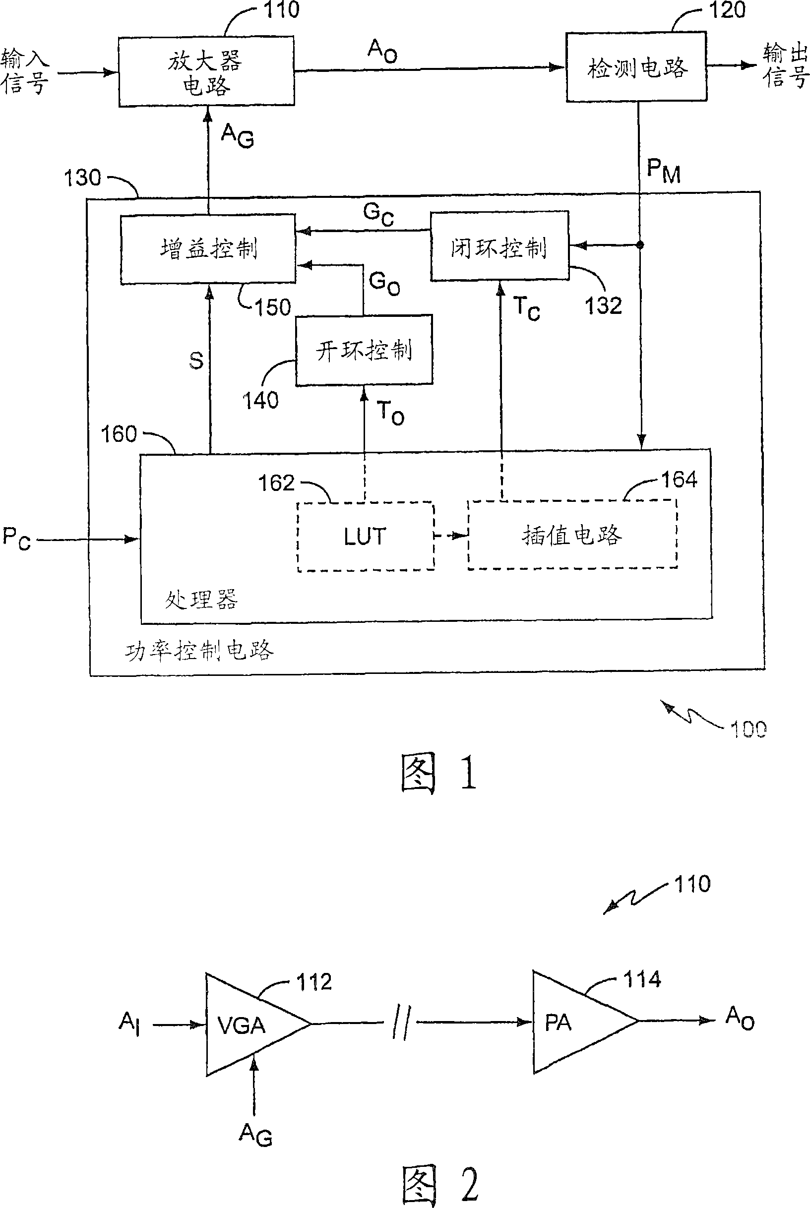
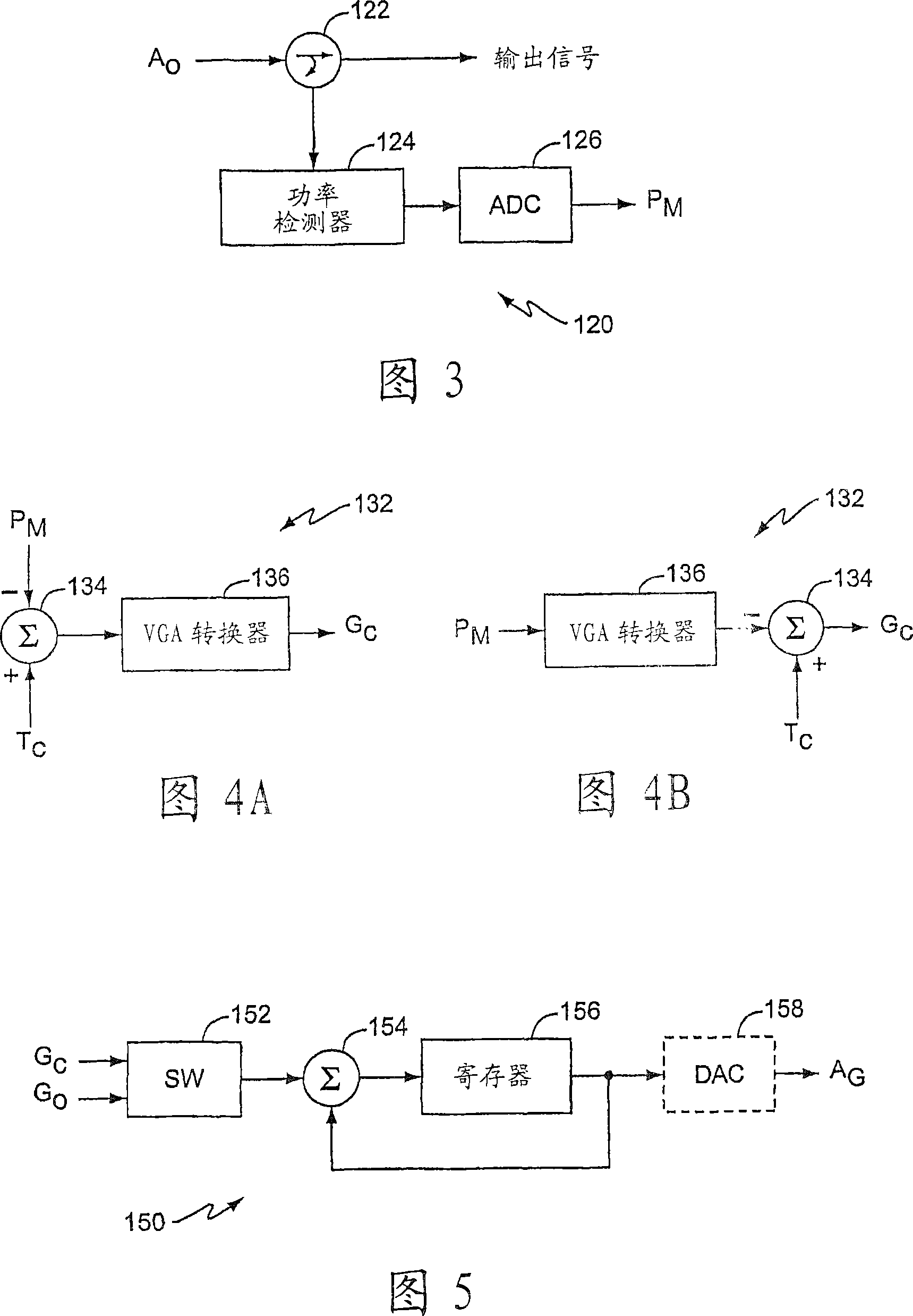
[0024] According to an exemplary embodiment, the amplification system 100 includes: an amplifier circuit 110 , a detection circuit 120 and a digital power control circuit 130 . Amplifier circuit 110 is responsive to gain control signal A provided by power control circuit 130 G while amplifying the input signal to obtain the desired power level of the amplified signal A O . The detection circuit 120 extracts the amplified signal A O A small part of , measure the power of the extracted part, and the measured power P M Provided to the power control circuit 130. Additionally, the detection circuit 120 provides an output signal for the amplifier system 100 . The power control circuit 130 responds to the power control command and / or the measured power P from the detection circuit 120 M , generating the gain control signal A G .

[0025] As shown in FIG. 2, the amplifier circuit 110 includes at least one variable gain amplifier (VGA) for amplifying an input signal to obtain an...


PUM


Abstract

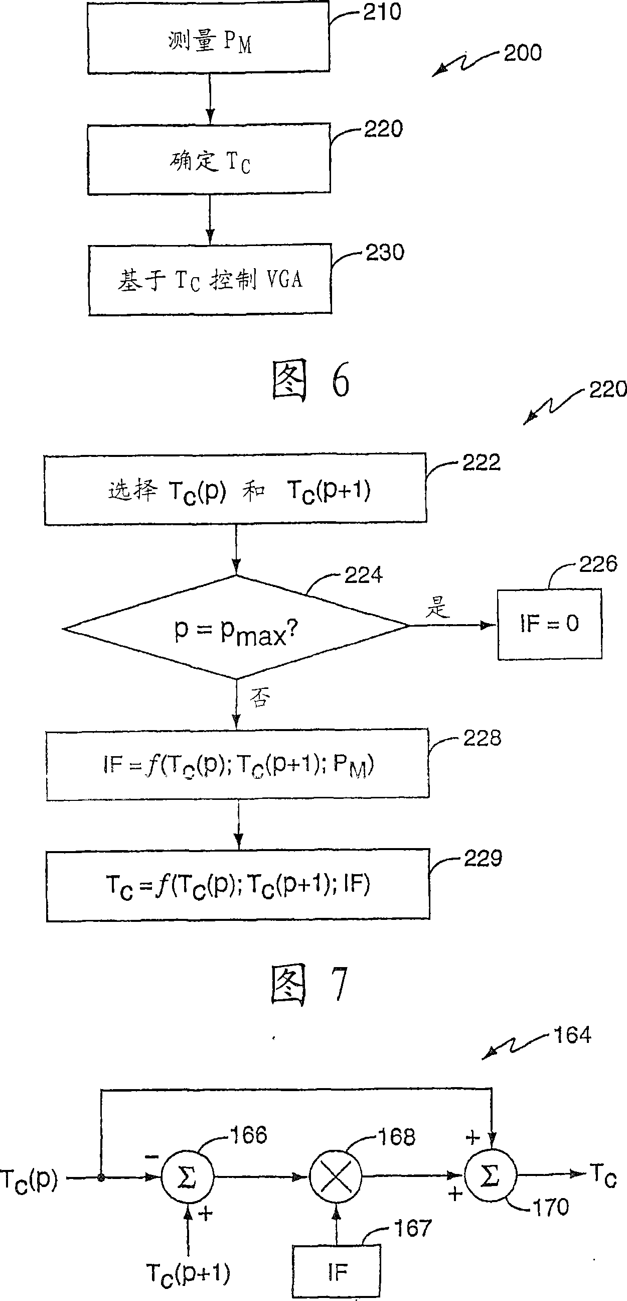
The present invention comprises a method and apparatus for continuously controlling a gain of an amplifier circuit while switching between open-loop and closed-loop power control. A control circuit controls the gain of the amplifier circuit during open-loop and closed-loop power control modes based on selected references. Before the switch from open-loop to closed-loop power control, the control circuit determines a closed-loop reference based on a power measured at the amplifier circuit output before the switch. After the switch, the control circuit controls the gain of the amplifier circuitbased on the determined closed-loop reference. Before switching from closed-loop to open-loop power control, the control circuit generates a difference between a current open-loop reference and a previous open-loop reference. After the switch, the control circuit controls the gain of the amplifier circuit based on an open-loop gain control signal generated by applying the difference to a previousclosed-loop gain control signal.

Description

technical field [0001] The present invention relates generally to power control for wireless transmitters, and more particularly, to variable gain amplifier circuits for wireless transmitters. Background technique [0002] Wireless communication systems employ power control to reduce interference and increase system capacity while maintaining minimum signal quality standards. The capacity of a wireless communication system (ie, WCDMA (Wideband Code Division Multiple Access) system) mainly depends on the precise execution of uplink power control. Many wireless communication standards such as 3GPP TS25.101 include specific requirements for transmission power control accuracy in wireless communication devices. These equipment requirements include absolute accuracy transfer power requirements and relative accuracy transfer power requirements. Absolute requirements define the lower and upper limit transmit power relative to the rated transmit power. Relative requirements defin...

Claims


Application Information

Patent Timeline
Patent Type & Authority Applications(China)
IPC IPC(8): H04B7/005
CPCH04W52/52H04W52/225H04W52/10H04W52/08H04W52/228H04W52/221H03G3/20H04B7/005
Inventor 比约恩·古斯塔夫松马丁·阿克贝里
Owner TELEFON AB LM ERICSSON (PUBL)
Learn More