
Driving means for belt gripper or rod of gripper loom

A technology of rapier looms and driving devices, applied in the field of driving devices and rapier looms, can solve the problems of high manufacturing cost, high material requirements, and many transmission links, etc., and achieve convenient processing of parts, simple and compact structure, and stable movement reliable effect

Inactive Publication Date: 2008-02-06
NO 4 TEXTILE MACHINERY MFG CO LTD JIANGYIN CITY
View PDF0 Cites 11 Cited by
  • Summary
  • Abstract
  • Description
  • Claims
  • Application Information

AI Technical Summary

Problems solved by technology

Among them, the size of the first three kinds of driving devices is too large, there are many transmission links, the number of parts is large, the manufacturing cost is high, and the installation and debugging are difficult; in the latter combination device of the screw pair and the connecting rod, the manufacturing accuracy of the variable pitch screw is high. The material requirements are also high, and the process is difficult, which makes the manufacturing cost high

Method used


Image

  • Driving means for belt gripper or rod of gripper loom
  • Driving means for belt gripper or rod of gripper loom
  • Driving means for belt gripper or rod of gripper loom

Examples


Embodiment 1

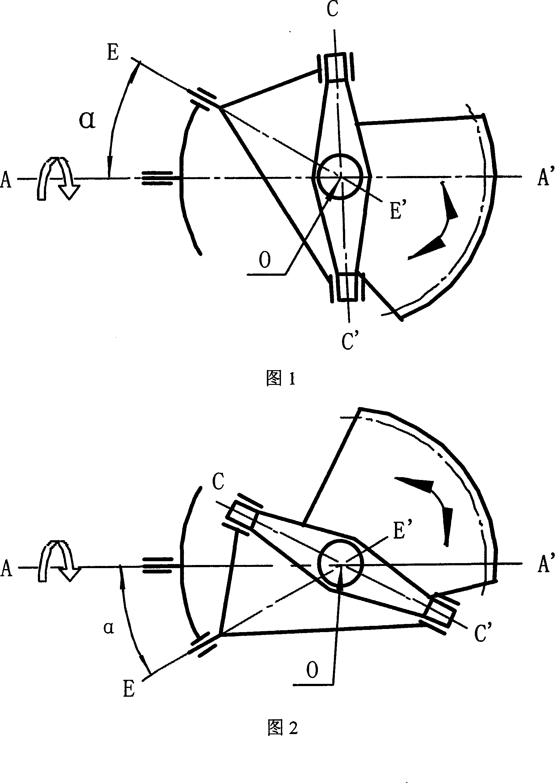
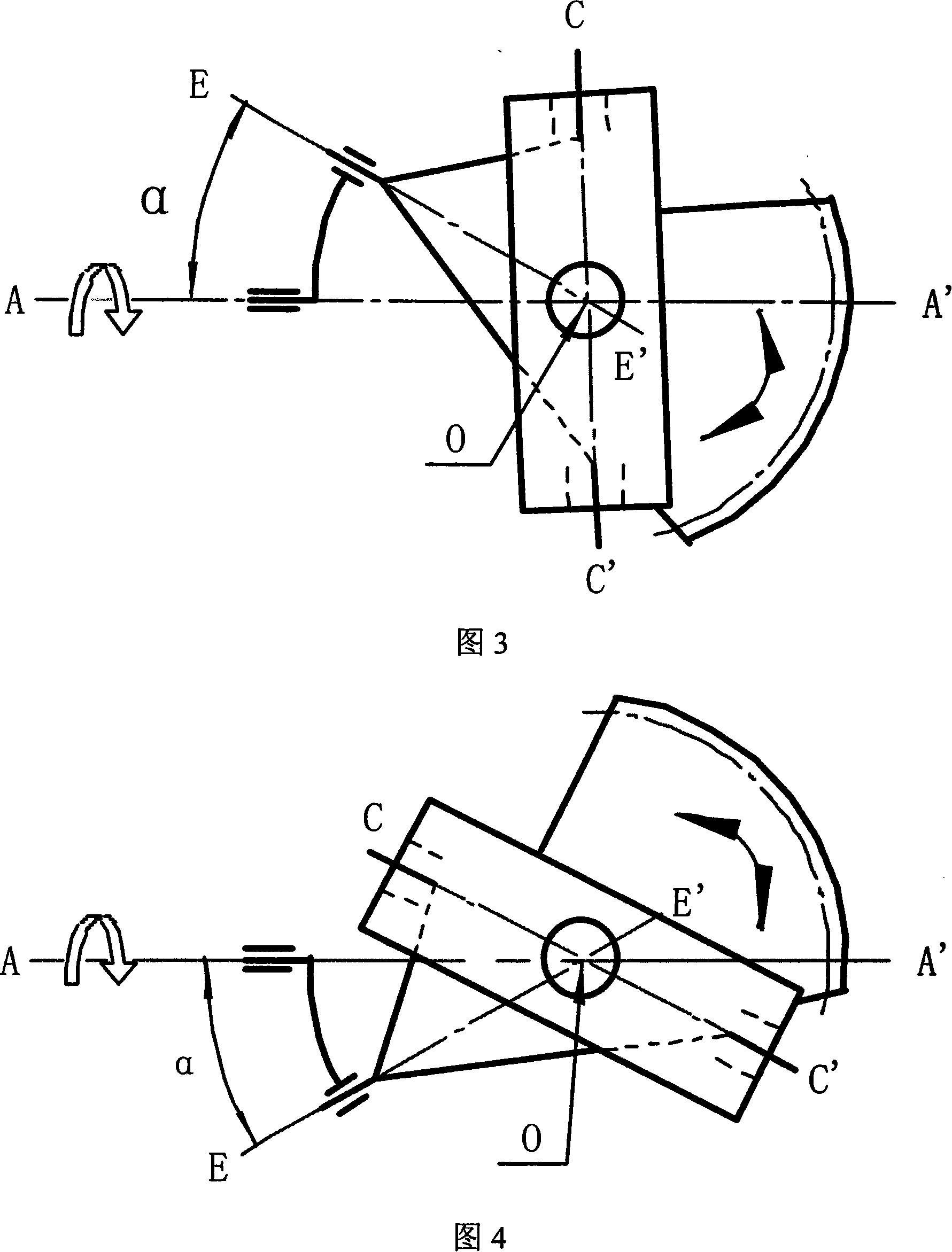
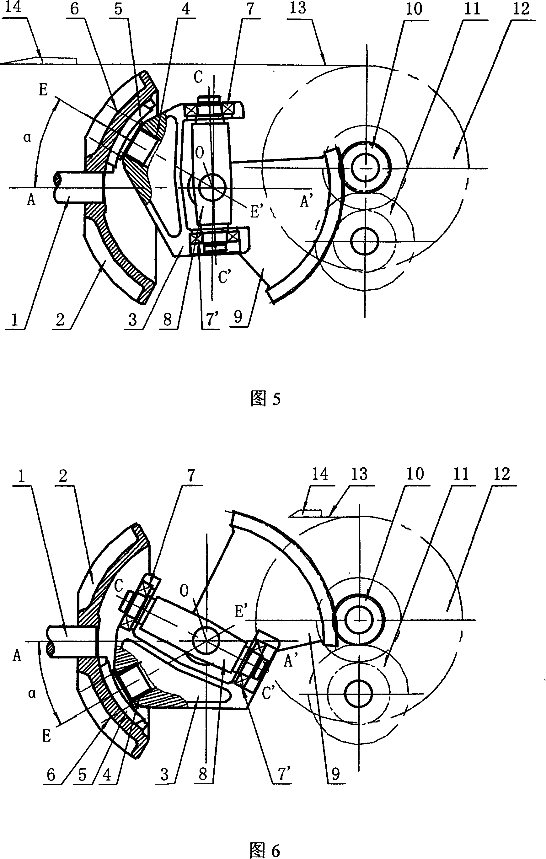
[0029] As shown in Fig. 5 and Fig. 6, the present invention is a driving device for a rapier or a rapier of a rapier loom. constitute. Wherein, the crank rocker mechanism is mainly composed of a crank 2 , a cradle 3 , a swing body 8 and a sector gear 9 . The crank 2 is connected with one end of the main shaft 1, the cradle 3 is connected with the crank 2 through the rolling bearing 4, the slider 5 and the screw 6, the oscillating body 8 is connected with the cradle 3 through the rolling bearing 7, the rolling bearing 7', and the oscillating body 8 is fixed with a sector The gear 9, the sector gear 9 meshes with the shaft gear 10, or the sector gear 9 meshes with the shaft gear 10 through the gear pair 11, the shaft gear 10 is coaxial with the transfer sword wheel 12, and the transfer sword wheel 12 is the driving part of the sword belt or rapier . The central axis AA' of the main shaft 1, the rotational axis EE' of the cradle 3, the central axis CC' of the oscillating body 8...

Embodiment 2

[0034] Referring to Fig. 7 and Fig. 8, the difference between this embodiment and embodiment 1 is that: a slot hole is provided in the crank 2, and the slider is fixedly connected in the slot hole with a screw 6.

Embodiment 3

[0036] Referring to Fig. 9 and Fig. 10, the difference between this embodiment and embodiment 1 lies in that the structure of the mounting seat hole and the mounting shaft of the rolling bearing connecting the cradle 3 and the swing body 8 are different.


PUM


Abstract

The present invention relates to a rapier tape or rapier driving device for rapier loom, and comprises a main shaft (1), a shaft gear (10) and a rapier transmitting wheel (12), wherein the shaft gear is coaxial to the rapier transmitting wheel; the main shaft (1) connects with a crank-rocker mechanism. The crank-rocker mechanism comprises a crank (2), a cradle (3), a swinging body (8) and a sector gear (9), wherein the crank is in fixed connection with the main shaft; the cradle connects with the crank via a roller bearing (4) and a slider (5); the swinging body connects with the cradle via the roller bearing; the sector gear is fixed on the swinging body and engaged with the shaft gear (10). The central axial line of the main shaft, the rotating axial line of the cradle, the central axial line of the swinging body and the swinging center of the sector gear meet at the same point in a space. The rotating axial line of the cradle and the central axial line of the main shaft have over-zero degree included angle (alpha), which can be adjusted to change the traverse or the position of the rapier tape or the rapier. The present invention can drive the rapier tape or the rapier to do reciprocal linear movements and has the advantages of simple and compact structure as well as stable and reliable movements.

Description

technical field [0001] The present invention relates to a rapier loom, in particular to a driving device for a rapier belt or a rapier of a rapier loom. The invention belongs to the technical field of looms of textile machinery. Background technique [0002] In the prior art, the weft insertion process of the rapier loom consists of two rapier heads that move relatively reciprocating linearly along the reed width of the loom, and move from both sides of the loom to the center of the shed of the loom. Weft yarn, and then return to the starting position on both sides, thus completing a weft insertion. Among them, the rapier head is fixed on the rapier belt or rapier, and the tooth holes on the rapier belt or rapier are driven by meshing with the teeth on the rapier wheel, or the end of the smooth rapier belt is fixed on the rapier wheel. Sword wheel drive. The key function of the rapier belt or rapier driving device of the rapier loom is to convert the uniform rotational mo...

Claims


Application Information

Patent Timeline
IPC IPC(8): D03D47/27
CPCD03D47/271D03D47/272D03D47/275
Inventor 程垂璋洪海沧曹亚洪程小军
Owner NO 4 TEXTILE MACHINERY MFG CO LTD JIANGYIN CITY
Learn More