
High-altitude framework type simple plate supporting machine

A frame-type, simple technology, applied in the direction of erection/assembly of bridges, bridges, buildings, etc., can solve the problems of enlarging the design section, common force, cumbersome construction, etc.

Active Publication Date: 2008-02-06
THE FOURTH ENG CO LTD OF CHINA ZHONGTIEMAJOR BRIDGE ENG GRP
View PDF0 Cites 9 Cited by
  • Summary
  • Abstract
  • Description
  • Claims
  • Application Information

AI Technical Summary

Problems solved by technology

However, in the construction of a large-scale bridge with a large concrete bridge deck structure (11.52x5.62m) and a large weight (400KN), if the truck crane is used to erect the beam on the bridge surface, there are the following defects: because the bridge deck structure is large in size, the use of When working with a single mobile crane (limited by the conditions on the bridge surface, the side slab can only be erected with a single crane), the working radius is at least 9m, so a car crane with a rated lifting capacity of more than 100t is required Carry out slab erection work; since the concrete bridge deck at the crane station on the bridge deck has not yet been poured in-situ with wet joints, it cannot form a slab truss structure with the steel truss girder to bear the force together, so it can only be used on three sides (or four sides) ) supported simply supported slabs to check the force of the concrete bridge deck construction state. It should be said that the design of the concrete bridge deck in this construction scheme is controlled by the construction load, and the design section needs to be enlarged; it is limited by the working radius of the mobile crane , each time a concrete bridge deck is erected, the crane needs to adjust its position once, and the 4 concrete deck panels in each section cannot be erected in place at one time, and the construction is more cumbersome

Method used


Image

  • High-altitude framework type simple plate supporting machine
  • High-altitude framework type simple plate supporting machine

Examples


Embodiment Construction

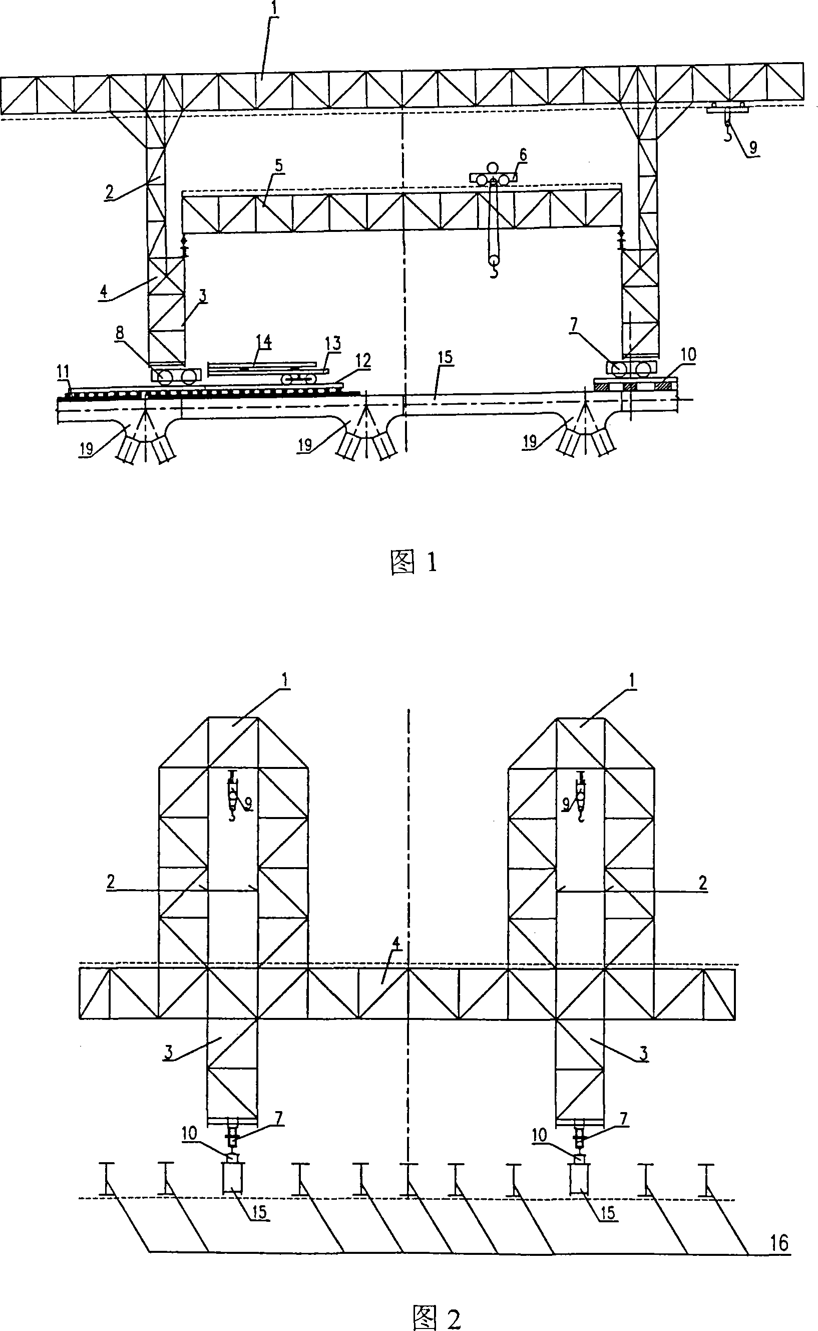
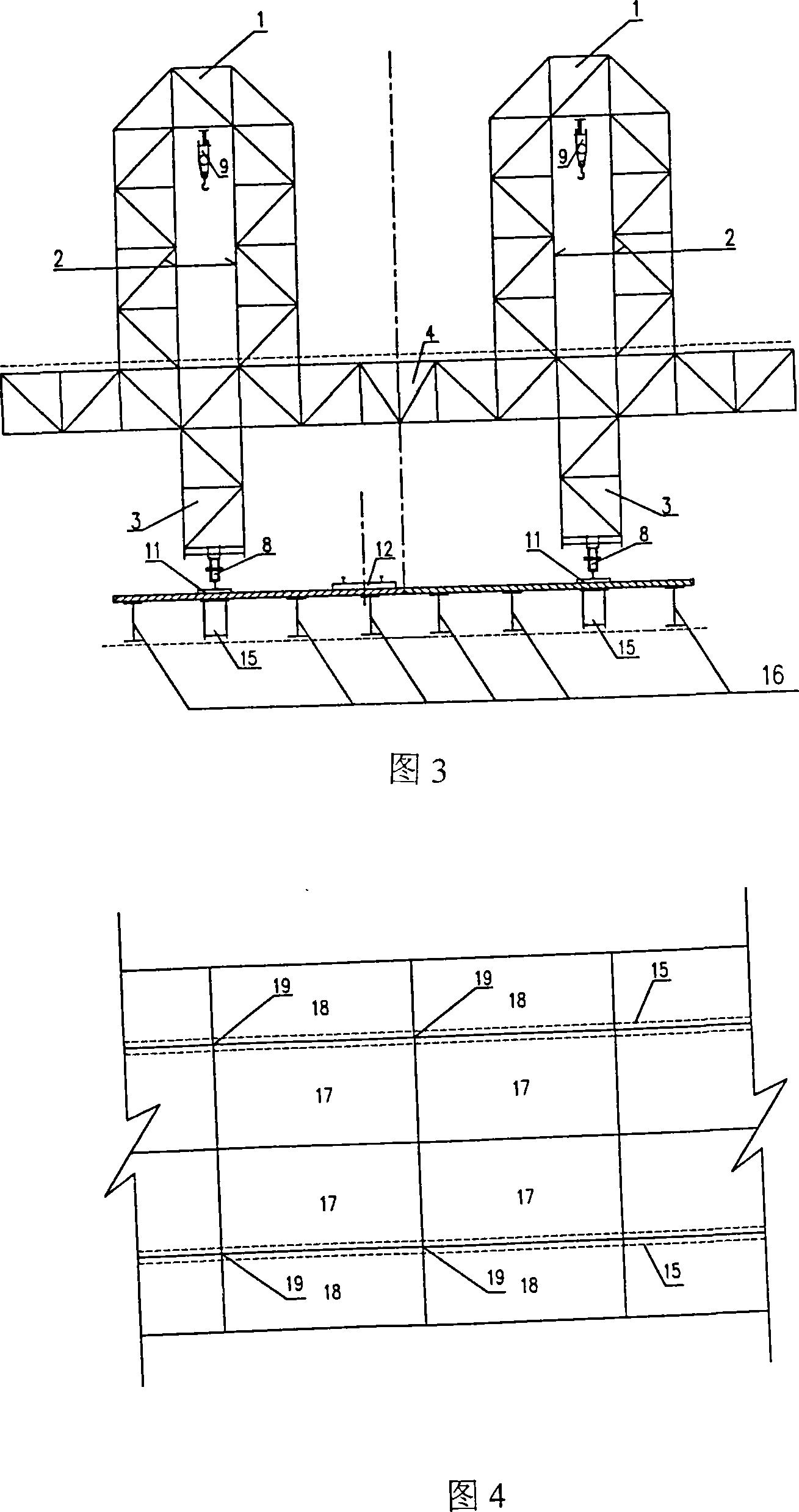
[0011] Referring to the accompanying drawings, its structure includes gantry connecting beam 1, gantry upper column 2, gantry lower column 3, lifting truss aisle beam 4, lifting truss 5, lifting trolley 6, and running system; wherein the gantry The connecting beam 1 is connected with the upper column 2 of the gantry, the upper column 2 of the gantry is connected with the aisle beam 4 of the hoisting truss, the aisle beam 4 of the hoisting truss is connected with the lower column 3 of the gantry, and the lifting trolley 6 is set on the lifting platform. On the truss 5, the front and rear end points of the lifting truss are located on the aisle beam 4 of the lifting truss, and the front traveling wheel box group 7 and the rear traveling wheel box group 8 in the traveling system are arranged under the lower column 3 of the gantry; The upper chords of the steel truss girders are connected as a whole through the upper chord nodes. The front wheel box group 7 in the running system tr...


PUM


Abstract

The present invention relates to a high altitude frame simple machine for an erecting plate, the structure is stated below: a gantry binding beam is connected with an upper column of the gantry, which is connected with a walkway beam of a hoisting truss, which is connected with a lower column of the gantry. The hoisting trolley is arranged on the hoisting truss. The front end and the rear end of the hoisting truss are positioned on the hoisting truss. A front walking wheel box group and a rear walking wheel box group are arranged under the lower column of the gantry; the front walking wheel box group and the rear walking wheel box group are arranged at a walkway of a transportation board of a trolley and a front walking wheel rail and a rear walking wheel are arranged at the lower position of the walkway of the transportation road; a plurality of upper stringer joints of the steel truss are arranged on an upper stringer rod of the steel truss, a longitudinal beam of the steel truss beam is connected with the upper string rod of the steel truss beam, and an electric hoist is positioned at the bottom of the gantry binding beam. The present invention has the advantages of free transverse and longitudinal travel, four concrete bridge decks between joints are erected one time; normal universal rod structures are used to make a frame structure. the present invention has the advantages of sound stability, high air-load resistance, short manufacturing time and low production cost, easy and convenient use.

Description

technical field [0001] The invention relates to a high-altitude frame-type simple lifting machine, which belongs to the technical field of high-altitude frame-type lifting machines. Background technique [0002] Usually, when the concrete bridge deck of the slab-truss composite structure beam is of appropriate size, small self-weight, and low pier height, the first few sections are erected on the ground with a crane, and the tire-type truck crane is hoisted to the bridge. The front concrete bridge deck is erected on the surface. However, in the construction of a large-scale bridge with a large concrete bridge deck structure (11.52x5.62m) and a large weight (400KN), if the truck crane is used to erect the beam on the bridge surface, there are the following defects: because the bridge deck structure is large in size, the use of When working with a single mobile crane (limited by the conditions on the bridge surface, the side slab can only be erected with a single crane), the ...

Claims


Application Information

Patent Timeline
IPC IPC(8): E01D21/00
Inventor 刘俊曹春元孙黄花欧阳平黄江刚余本俊朱琪贾珍程晨张武
Owner THE FOURTH ENG CO LTD OF CHINA ZHONGTIEMAJOR BRIDGE ENG GRP
Learn More