Railway motor trolley power-driven bi-parting sliding plug door system
A technology for rail trains and sliding doors, applied in door devices, vehicle locks, windows/doors, etc., can solve the problems of increasing the technical difficulty of the door system, unable to meet the needs of the society, increasing the opening degree, etc., and achieve installation, commissioning and maintenance. The effect of convenience, large carrying capacity, increased safety and reliability
- Summary
- Abstract
- Description
- Claims
- Application Information
AI Technical Summary
Problems solved by technology
Method used
Image

Examples
Embodiment Construction
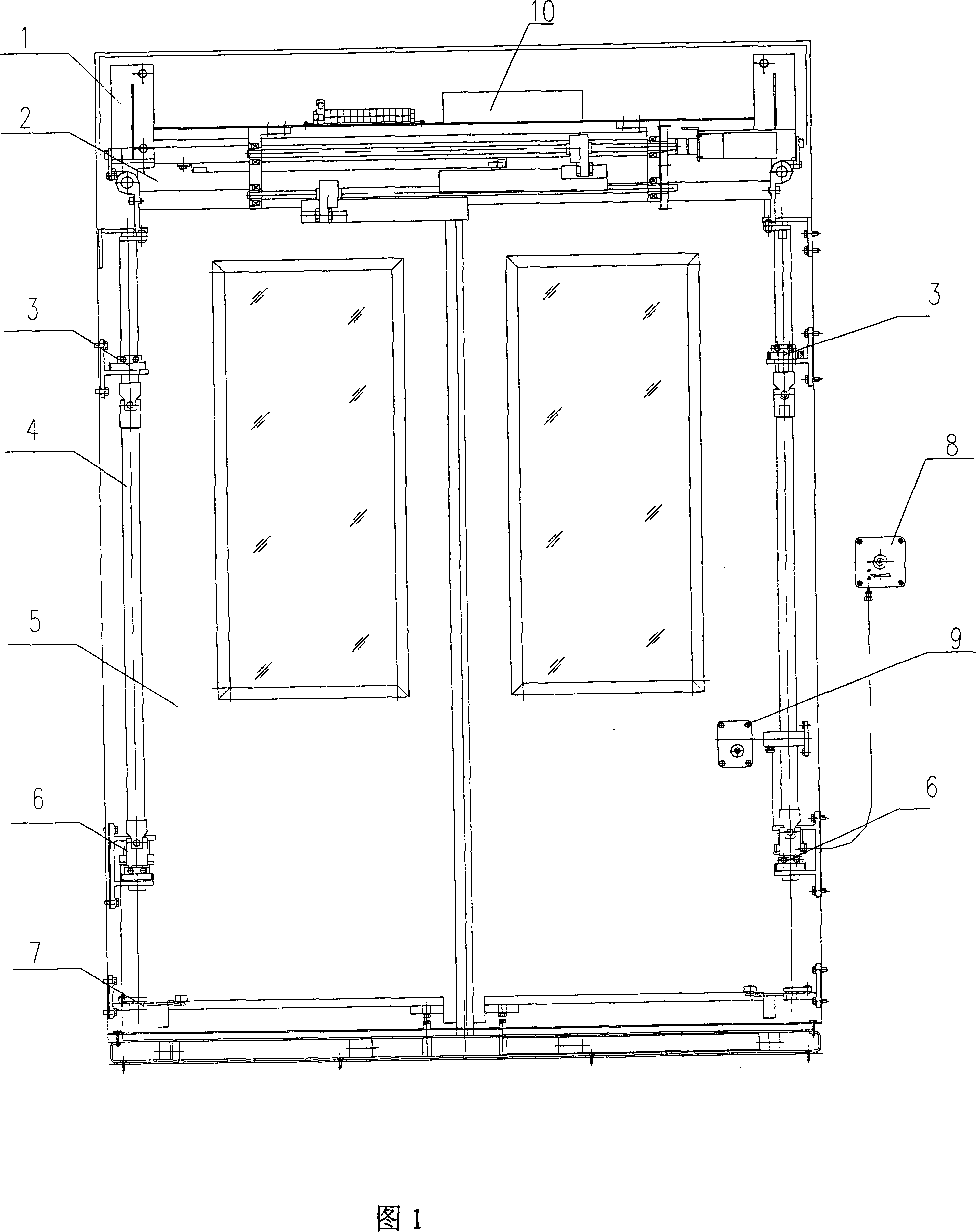
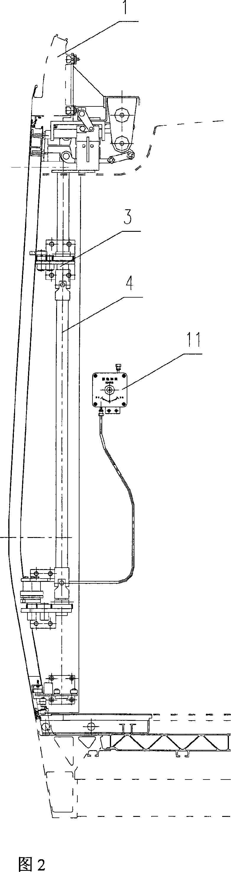
[0011] Referring to the accompanying drawings, its structure is that the load-bearing drive mechanism 2 is installed on the top of the car body 1, and the door leaf 5 is connected with the load-bearing drive mechanism 2 through the door frame; connected, and installed on both sides of the car body 1 after being connected with the locking device 6 at the middle and lower part of the car door, the rollers in the lower swing arm mechanism 7 are in the lower guide rail at the bottom of the car door; the outer operating device 8 installed on the outside of the car body 1 and The emergency operating device 11 installed inside the vehicle body 1 is connected to the locking device 6 through a wire rope;
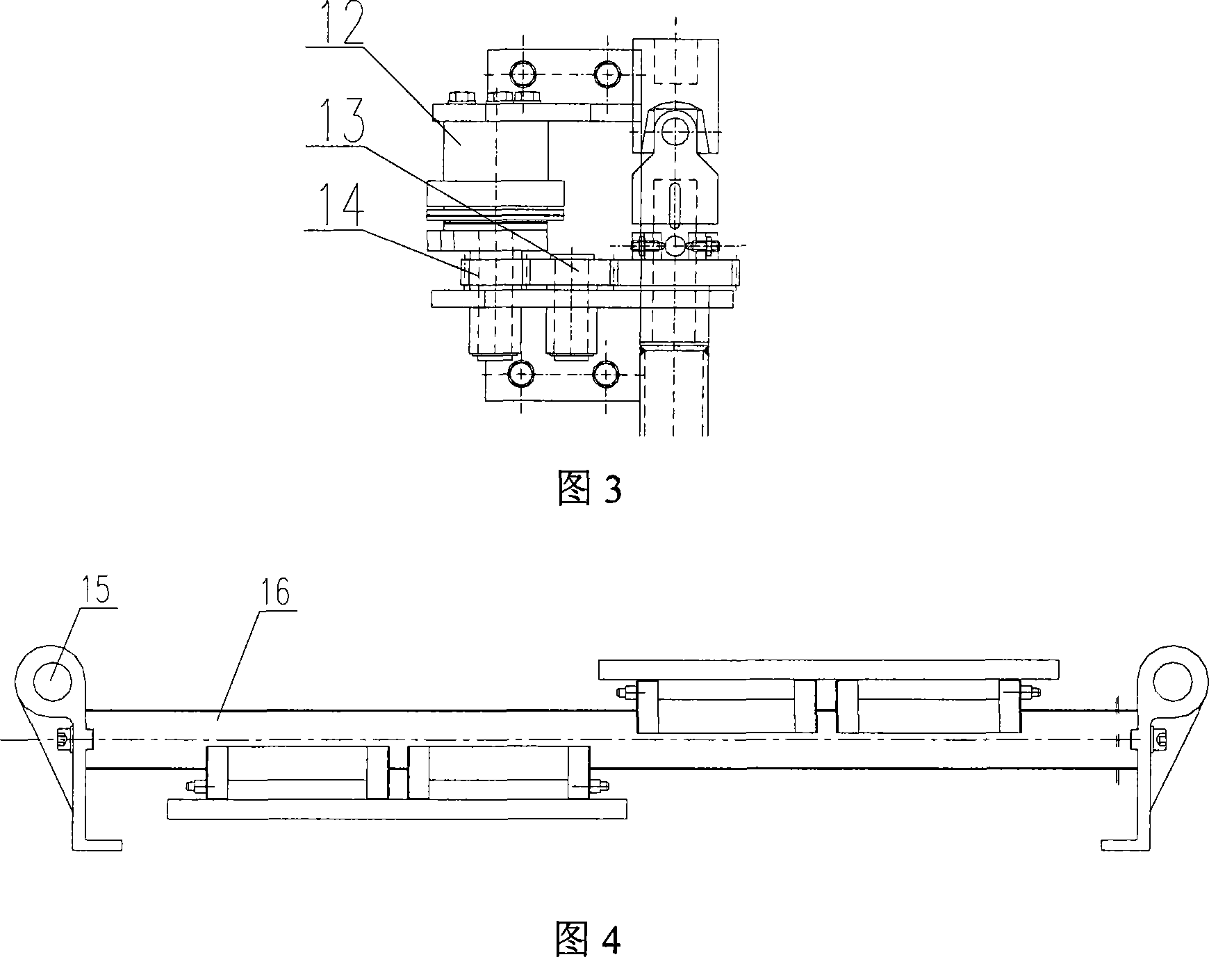
[0012] The upper slideway in the load-carrying drive mechanism 2 is installed on the base plate, and the left and right short guide posts on both sides of the upper slideway are respectively installed on the base plate through brackets, and a hanger is respectively installed on the le...
PUM
 Abstract
Description
Claims
Application Information
PatSnap Eureka turns technology decisions into work you can execute. Powered by our Innovation Knowledge Graph, it runs expert workflows across engineering, life sciences, materials and intellectual property. Get your review-ready output in minutes.


