Minisize transformer device and manufacturing method therefor

A technology of a micro-transformer and a manufacturing method, which is applied to the manufacture of inductors/transformers/magnets, transformers/inductor cores, electrical components, etc., can solve the problems of inconvenient assembly, high defect rate, complex production process, etc., and achieve simplification Process, the effect of reducing production and assembly costs

Inactive Publication Date: 2008-02-06
DELTA ELECTRONICS INC
View PDF0 Cites 0 Cited by
  • Summary
  • Abstract
  • Description
  • Claims
  • Application Information

AI Technical Summary

Problems solved by technology

The structure of the existing transformer, as shown in Fig. 1 and Fig. 2, adopts two independent base bodies 7, 8 and the iron core to form after assembly, it has the following disadvantages, the two independent base bodies 7

Method used


Image

  • Minisize transformer device and manufacturing method therefor
  • Minisize transformer device and manufacturing method therefor
  • Minisize transformer device and manufacturing method therefor

Examples


Embodiment Construction

[0015] A microtransformer and its manufacturing method according to a preferred embodiment of the present invention will be described below with reference to related drawings.

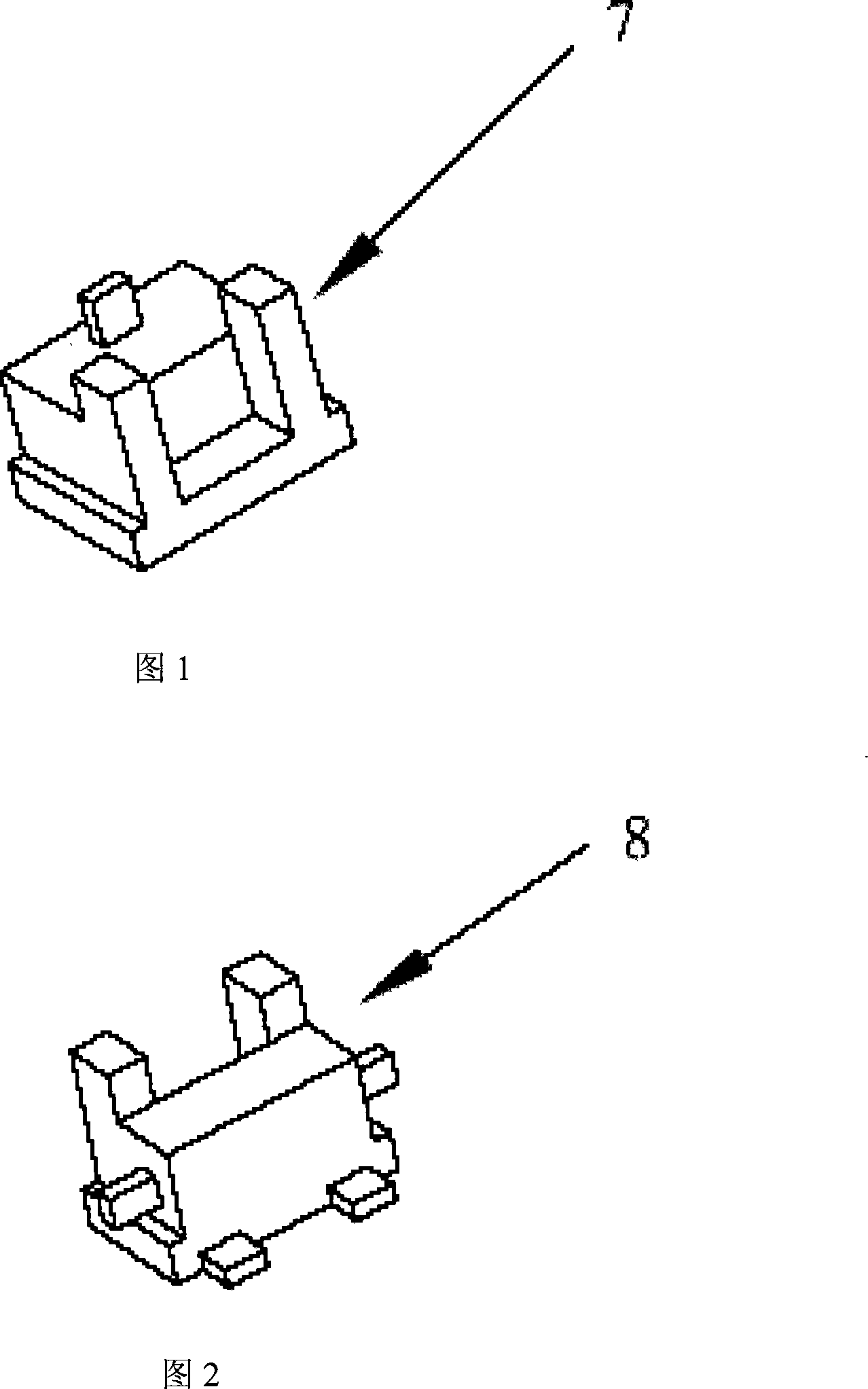
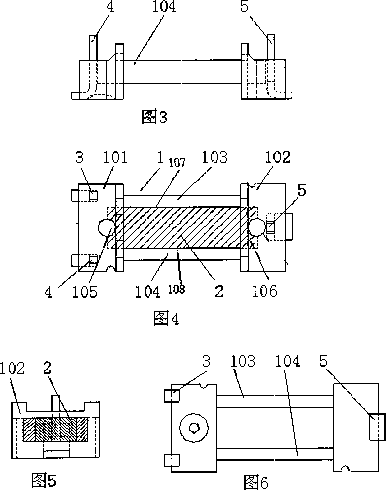
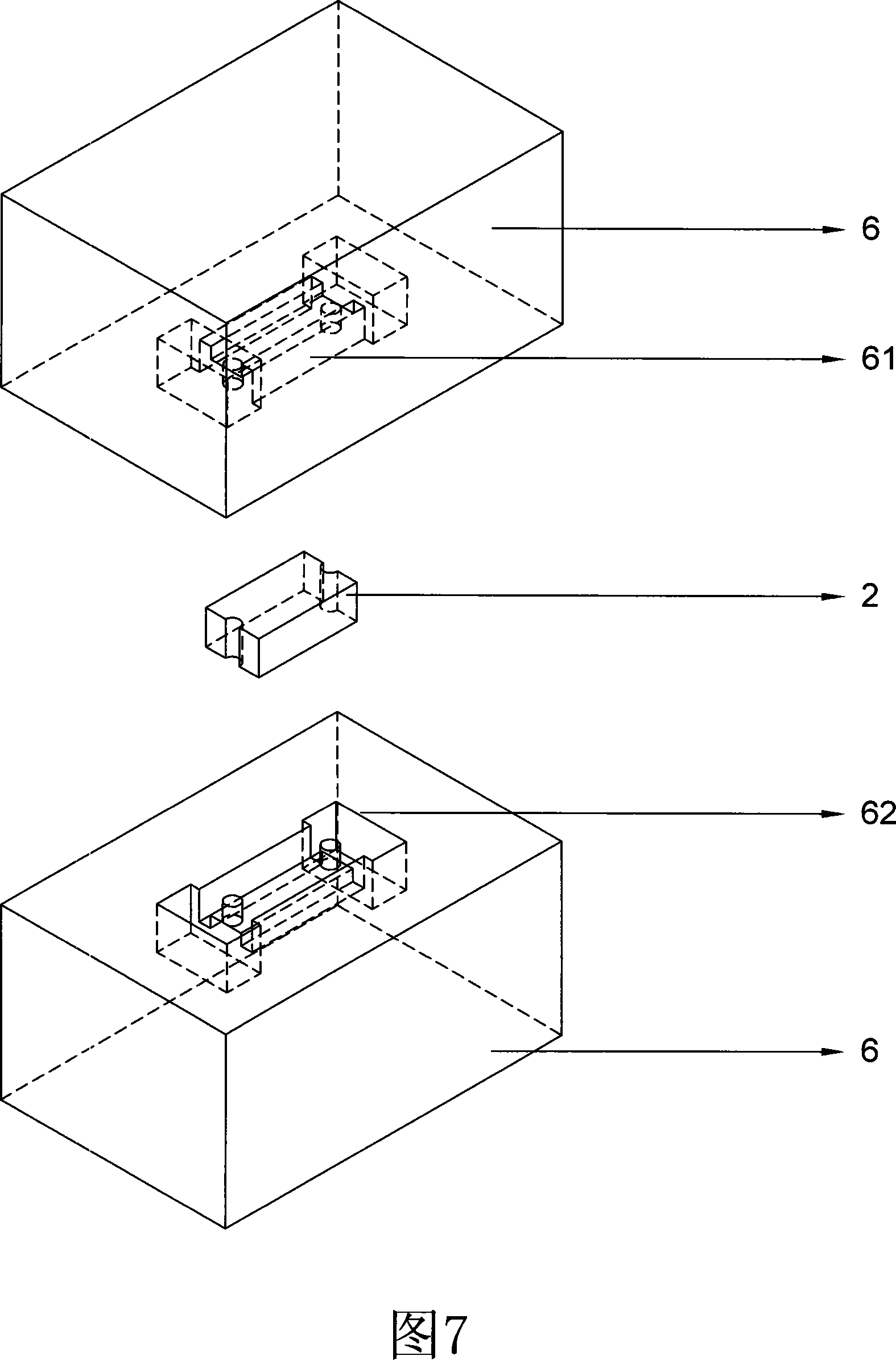
[0016] With reference to Fig. 3, Fig. 4, Fig. 5, Fig. 6, Fig. 7, a kind of miniature transformer of preferred embodiment of the present invention is provided with transformer reel 1, transformer iron core 2. Wherein, the transformer iron core 2 is made of elongated magnetic material, the two ends of the transformer reel 1 have flanges 101, 102, the flanges 101, 102 cover the two short ends 105, 106 of the transformer iron core 2, and the flanges The parts 101 and 102 are connected as a whole by two extension parts 103 and 104, the extension parts 103 and 104 cover the two long ends 107 and 108 of the transformer core 2, and the transformer reel 1 is directly molded and tightly covered by a single mold 6 Transformer iron core 2 surroundings.

[0017] The manufacturing method of a kind of miniature tran...


PUM


Abstract

The present invention discloses a production method for micro-transformers, and the method includes the following steps: an iron core, which has magnetic properties, is provided with a gap for fixing on a mould; the iron core is positioned into the mould; plastic is injected into the mould and is solidified so as to closely wrap the periphery of the iron core. A micro-transformer is provided, which comprises an iron core and a rolling spindle, wherein, the iron core is produced with magnetic material and is provided with a gap for fixing on the mould, and the rolling spindle closely wraps the periphery of the iron core. The rolling spindle is directly molded to bundle the periphery of the iron core by dint of a single mould. The present invention adopts the model of integrative forming to make the rolling spindle wrapped onto the periphery of the iron core, thereby simplifying manufacturing procedures, reducing the cost of production and assembly, avoiding the wanting in the process of assembling electronic components, and improving the reliability and the good yield of products.

Description

technical field [0001] The invention relates to a micro-transformer structure used in optical equipment such as cameras or small electronic equipment and a manufacturing method thereof. Background technique [0002] In the prior art, in some miniaturized or miniaturized digital products, it is necessary to use a transformer to boost the low voltage of the power supply battery to a high voltage in order to realize its functions, such as charging and flashing. Due to the size of digital products Small, so the volume of the transformer is very small and cannot take up too much space. The structure of the existing transformer, as shown in Fig. 1 and Fig. 2, adopts two independent base bodies 7, 8 and the iron core to form after assembly, it has the following disadvantages, the two independent base bodies 7, 8 and the iron core The assembly is inconvenient, the production process is complicated and the cost is high, and the characteristics of the finished product made with this ...

Claims


Application Information

Patent Timeline
IPC IPC(8): H01F41/00H01F27/24
Inventor 翟学勇
Owner DELTA ELECTRONICS INC
Why Eureka
Try Eureka