Method for manufacturing airtight cavity structure

A manufacturing method and air-tightness technology, applied in electrolysis process, electroforming and other directions, can solve the problems of inability to form, small capillary size, complicated manufacturing process, etc., and achieve the effect of simple process and good capillary effect.

Inactive Publication Date: 2008-07-30
FU ZHUN PRECISION IND SHENZHEN +1
View PDF3 Cites 9 Cited by
  • Summary
  • Abstract
  • Description
  • Claims
  • Application Information

AI Technical Summary

Problems solved by technology

The grooved capillary structure is limited by the manufacturing process, so it cannot form a small enough capillary size, and it is difficult to achieve a satisfactory capillary effect
However, the process

Method used


Image

  • Method for manufacturing airtight cavity structure
  • Method for manufacturing airtight cavity structure
  • Method for manufacturing airtight cavity structure

Examples


Example Embodiment

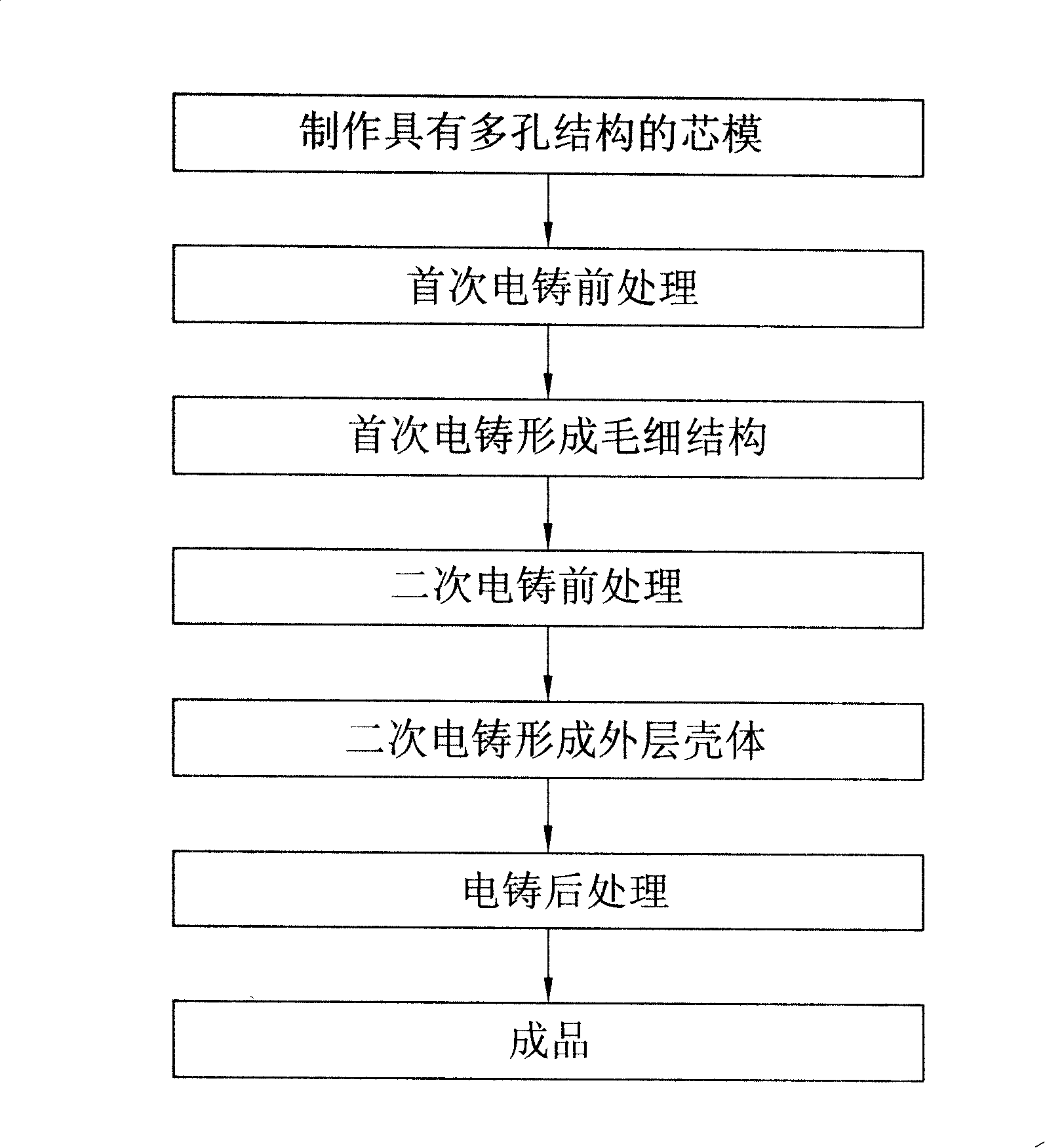
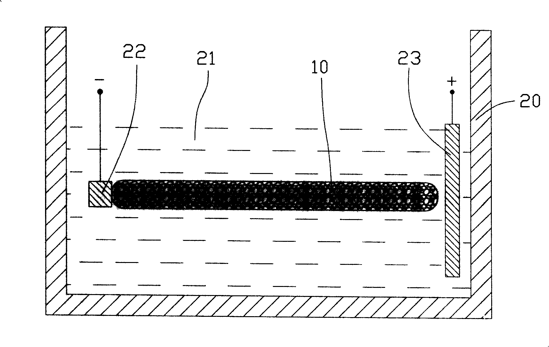
[0014] figure 1 Shown is a schematic flow chart of the manufacturing method of the airtight cavity structure of the present invention, which includes the following main steps: making a core mold with a porous structure → pre-treatment for the first electroforming → forming a capillary structure by the first electroforming → before the second electroforming Processing → secondary electroforming to form outer shell → electroforming post-processing → finished product.

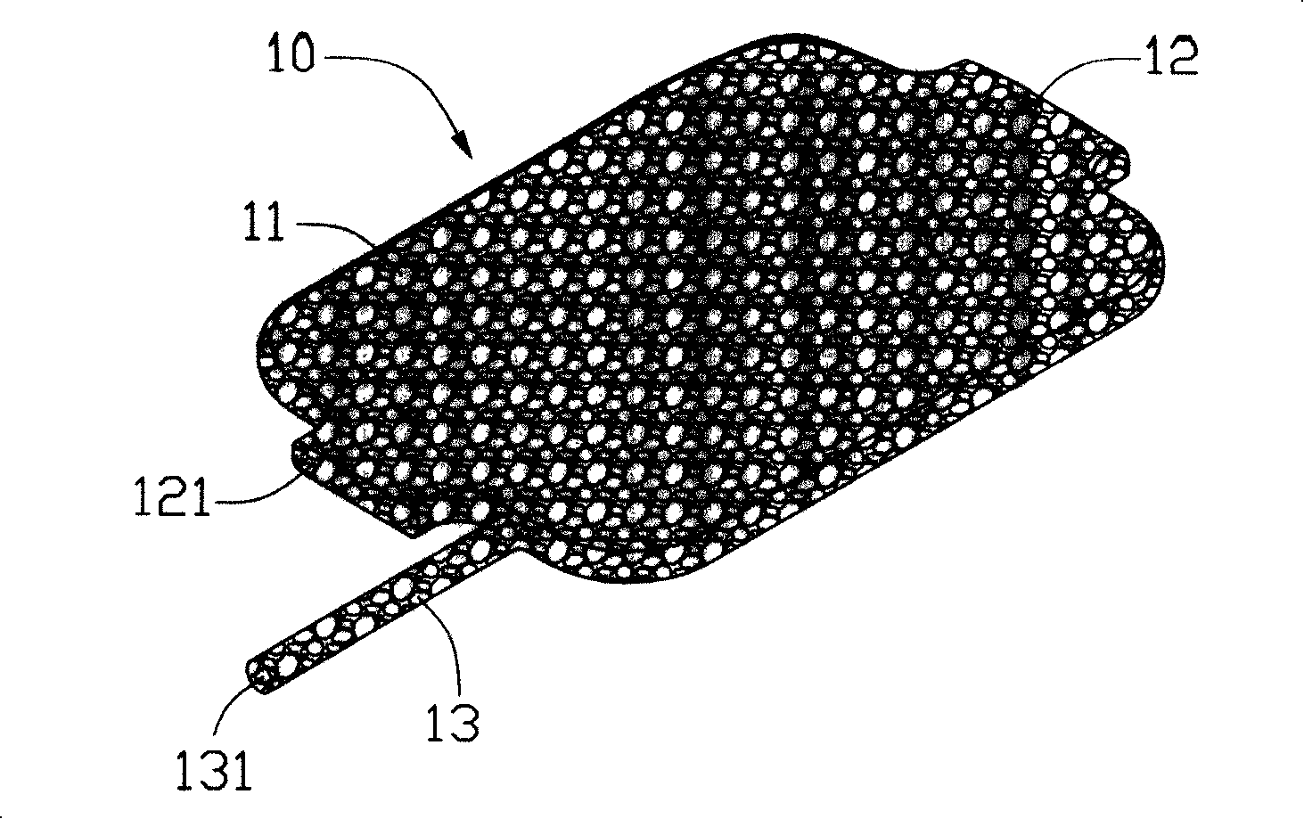
[0015] For brevity and convenience of description, the following is Figure 4 versus Figure 5 The airtight cavity structure 30 shown in is representative to illustrate the above-mentioned manufacturing method. Figure 4 versus Figure 5 It is a schematic diagram of the air-tight cavity structure 30 before being filled with working liquid and without being sealed. The air-tight cavity structure 30 includes a shell 31, a cavity 32 is formed in the shell 31, a porous capillary structure 33 is arranged on the entire inne...


PUM


Abstract

The invention relates to a method of manufacturing an airtight cavity structure and includes the following steps: firstly, a mandrel with a porous structure is manufactured, that is, a porous foam plastic framework is manufactured; secondly, an electric conduction treatment is conducted to the pore wall of the foam pore on the surface of the mandrel and at a predetermined depth under the surface of the mandrel; thirdly, the mandrel is electroformed for the first time and a first metal cast layer is formed on the surface of the mandrel and in the foam pore at the predetermined depth; fourthly, a surface polishing treatment is conducted to the mandrel electroformed for the first time to flatten and smooth the surface; fifthly, the mandrel is electroformed for the second time and a second metal cast layer is formed on the outer surface of the mandrel; sixthly, the mandrel is eliminated and a cavity body with the first metal cast layer as the capillary structure and the second metal cast layer as the shell body is obtained; and finally, an operating fluid is injected into the cavity body and an airtight cavity structure is thus obtained. The manufacturing method has simple manufacturing procedures and can mold an airtight cavity structure with preferable capillary effect.

Description

technical field [0001] The invention relates to a method for manufacturing an airtight cavity structure, in particular to a method for manufacturing an airtight cavity structure that utilizes the principle of phase change to dissipate heat. Background technique [0002] With the rapid development of the computer industry, more and more heat is generated by heating electronic components in notebook computers such as CPU and VGA. However, the shape design of notebook computers is developing in the direction of light, thin, short and small. The space is constantly shrinking, which puts forward higher requirements for the design of the cooling module in the notebook computer. In order to improve the heat exchange efficiency of the heat dissipation module in a small space, one of the methods currently adopted is to use an airtight cavity structure (Vapor Chamber) in the heat dissipation module. [0003] The main advantage of the airtight cavity structure is not only that its hea...

Claims


Application Information

Patent Timeline
IPC IPC(8): C25D1/08C25D1/10
Inventor 孟劲功黄清白
Owner FU ZHUN PRECISION IND SHENZHEN
Why Eureka
Try Eureka