Camshaft device and method of assembling camshaft device

An assembly method and camshaft technology, which can be applied to valve devices, shafts and bearings, valve driving devices, etc., can solve problems such as extra labor and increased manufacturing costs

Inactive Publication Date: 2008-02-06
JTEKT CORP
View PDF4 Cites 9 Cited by
  • Summary
  • Abstract
  • Description
  • Claims
  • Application Information

AI Technical Summary

Problems solved by technology

However, when the rolling bearing or the cam is press-fitted on the camshaft, since the rolling bearing or the cam must be fixed at a predetermined axial position, it takes a lot of time for assembly and the manufacturing cost increases.

Method used


Image

  • Camshaft device and method of assembling camshaft device
  • Camshaft device and method of assembling camshaft device
  • Camshaft device and method of assembling camshaft device

Examples


Embodiment Construction

[0041] Hereinafter, embodiments of the present invention will be described with reference to the drawings.

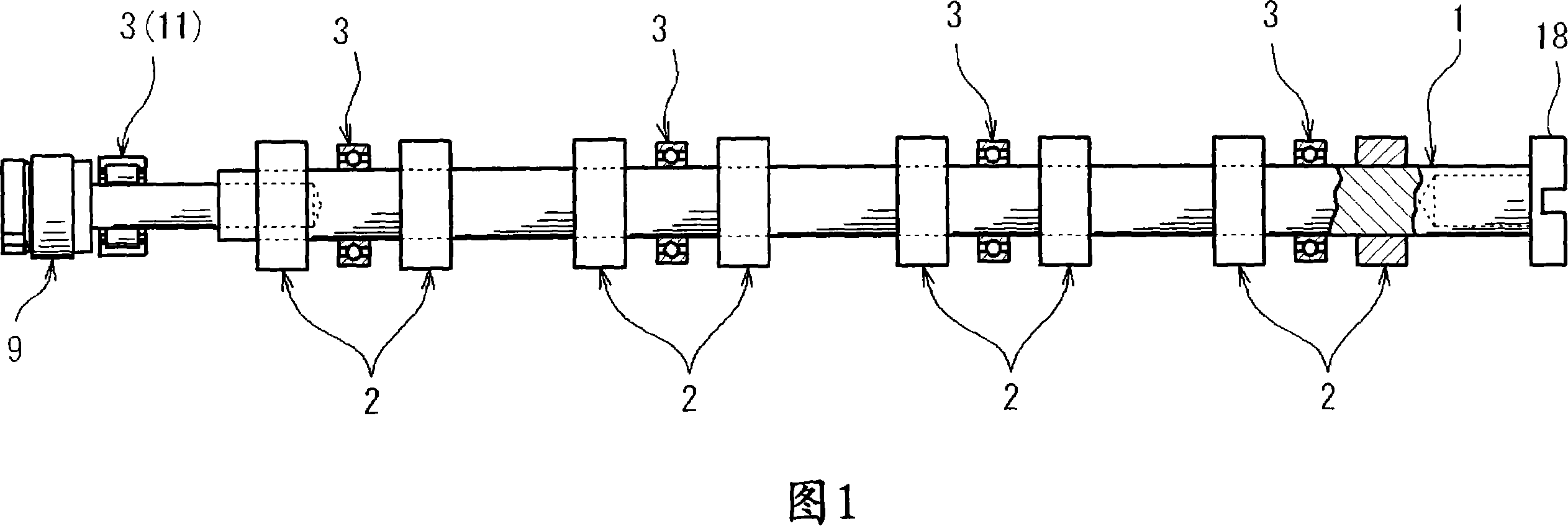
[0042] FIG. 1 is a side view showing a partial section of a camshaft device according to an embodiment of the present invention. This camshaft device can be applied, for example, to a camshaft mechanism for actuating intake and exhaust valves of an automobile engine. This device is formed by arranging a plurality of cams 2 and a plurality of rolling bearings 3 at predetermined positions in the axial direction of the camshaft 1 on the camshaft 1 . In addition, one rolling bearing 3 is provided between the cams 2 as a pair.

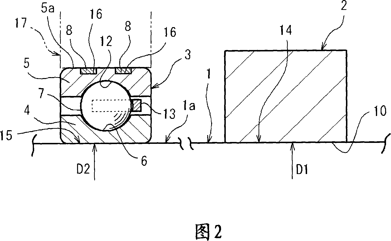
[0043] Fig. 2 is an enlarged cross-sectional view showing a main part of Fig. 1 . This device includes: a linear camshaft 1, an elliptical cam 2 that is separate from the camshaft 1 and mounted on the camshaft 1 in an external fit shape, and a plurality of rolling bearings 3 that rotatably support the camshaft 1. .

[0044] That is to say, the ca...


PUM


Abstract

A cam shaft assembly is provided which accomplishes torque reduction, which obviates a shortened service life of a bearing and which is designed to reduce a radial dimension with respect to the center of a cam shaft. The cam shaft assembly includes: the cam shaft (1); a cam 2 separate from the cam shaft (1) and including a through-hole so as to be fitted on the cam shaft (1); and a rolling bearing 3 including annular monolithic inner and outer rings and serving to rotatably support the cam shaft (1). The cam shaft (1) is formed in a linear structure which has the same diameter at its portion where the cam 2 is mounted and its portion where the rolling bearing 3 is mounted.

Description

technical field [0001] The present invention relates to a camshaft device in which a rotating shaft having a cam is supported by bearings and an assembly method thereof, and more particularly to a camshaft device which is rotationally driven synchronously with the rotation of an engine. Background technique [0002] Conventionally, as an example of a bearing structure for rotatably supporting a camshaft in a housing, there is known a sliding bearing structure in which a bearing portion of a housing directly supports the outer periphery of a journal portion of a camshaft. However, in this case, since the outer periphery of the journal portion is in direct contact with the bearing portion, there are problems such as short life and vibration. In order to solve such a problem, there is a structure in which a bearing is provided between the housing and the camshaft. [0003] For example, in an automobile engine, as a device for rotatably supporting a camshaft having a cam for op...

Claims


Application Information

Patent Timeline
Patent Type & Authority Applications(China)
IPC IPC(8): F01L1/04F16C35/063
CPCF16C35/06F01L1/047F16C2360/18Y10T29/49826Y10T74/2101
Inventor 上野弘山川和芳羽方稔博
Owner JTEKT CORP
Why Eureka
Try Eureka