Lift facility, belt for such a lift facility, method for manufacturing such a belt, combination of such a belt and method for assembling such a combination in a lift facility

A combination and elevator technology, applied to elevators, applications, belts and other directions in buildings, can solve the problems of increasing belt dynamic load, elevator equipment failure, noise, etc., to reduce shear deformation, improve service life, and suppress vibration effect

Inactive Publication Date: 2008-02-13
INVENTIO AG
View PDF2 Cites 16 Cited by
  • Summary
  • Abstract
  • Description
  • Claims
  • Application Information

AI Technical Summary

Problems solved by technology

On the other hand, in the case of excessively sharp wedge angles, it can occur that the belt jams in the groove of the pulley
As a stick-slip effect, this jamming excites the belt to generate undesired vibrations, which at the same time generate noise and increase the dynamic load of the belt and the risk of running off its guide rails
In this extreme case, this jamming can also lead to failure of the elevator system if the belt only jumps out of the groove of the pulley or does not leave the groove of the pulley at all.

Method used


Image

  • Lift facility, belt for such a lift facility, method for manufacturing such a belt, combination of such a belt and method for assembling such a combination in a lift facility
  • Lift facility, belt for such a lift facility, method for manufacturing such a belt, combination of such a belt and method for assembling such a combination in a lift facility
  • Lift facility, belt for such a lift facility, method for manufacturing such a belt, combination of such a belt and method for assembling such a combination in a lift facility

Examples


Embodiment Construction

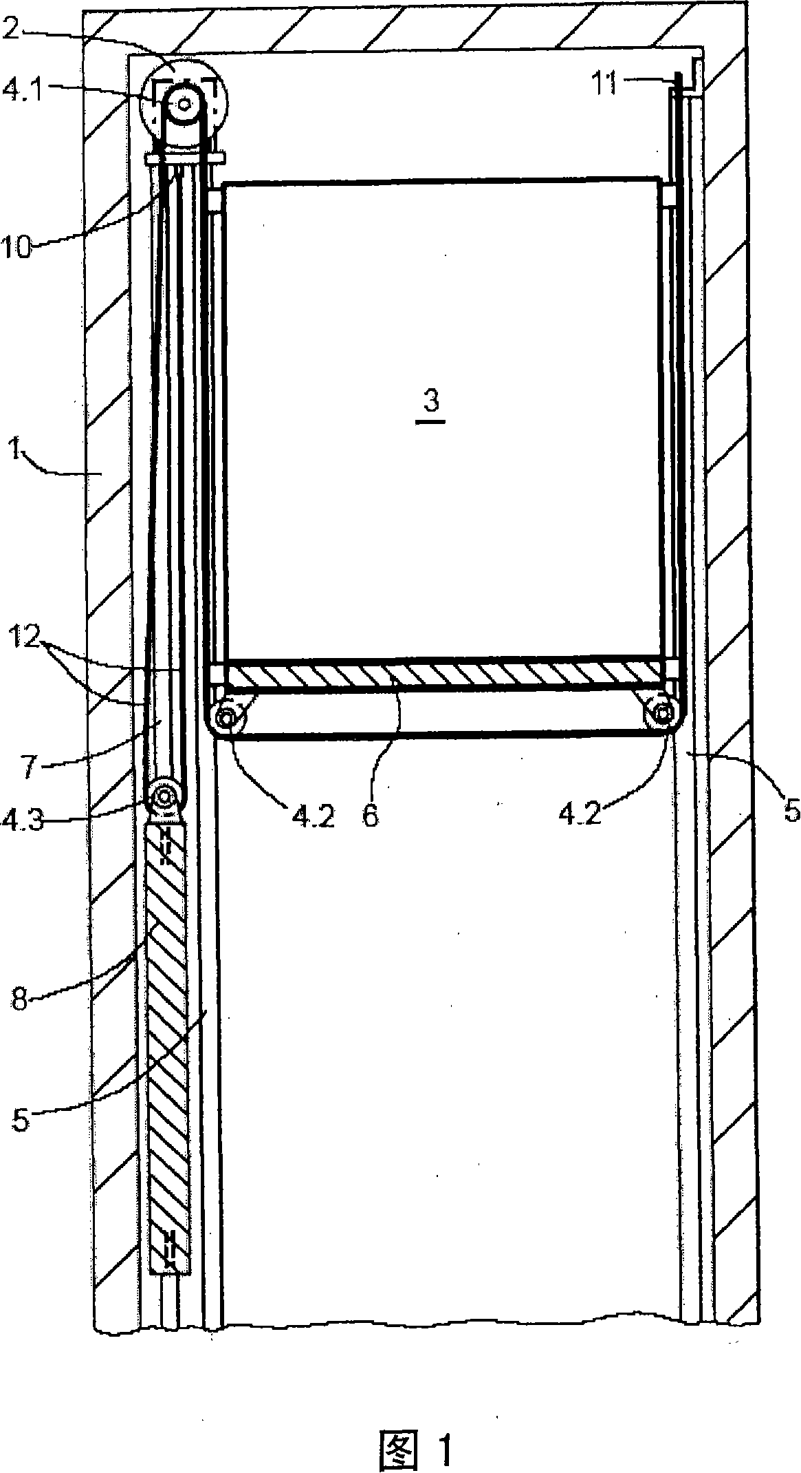
[0048] Figure 1 shows a cross-sectional view of an elevator installation installed in an elevator shaft 1 according to an embodiment of the present invention. The equipment includes: a driving device 2 fixed in the elevator shaft 1, the driving device 2 has a driving pulley or a driving shaft 4.1; the elevator car 3 guided at the car guide rail 5 has a car floor 6 The lower deflection roller, and the deflection roller takes the form of the car support roller 4.2; the counterweight 8 guided at the counterweight guide rail 7 has another deflection roller in the form of the counterweight support roller 4.3; and is configured as a wedge-shaped rib belt The support belt 12 is used for the elevator car 3 and the counterweight 8. This belt transmits the driving force from the drive pulley of the drive unit 2 or the drive shaft 4.1 to the elevator car and the counterweight.

[0049] Below the drive pulley or drive shaft 4.1, one end of the wedge-shaped rib belt 12 is fastened to the first...


PUM

PropertyMeasurementUnit
diameteraaaaaaaaaa

Abstract

A lift belt (12) for a lift installation comprises a belt body (15) in which a tensile carrier arrangement (14) with several tensile carriers (14.1, 14.2) for transmission of a tension force in longitudinal direction of the lift belt is arranged. A profile body (16) which spaces these tensile carriers from one another is arranged between adjacent tensile carriers (14.1, 14.2) of the tensile carrier arrangement (14). <SDOCL LA=EN> 12 Claims 1. Lift belt (12) for a lift installation, with a belt body (15) in which a tensile carrier arrangement (14) with several tensile carriers (14.1, 14.2) in the form of strands or cables for transmission of a tension force in longitudinal direction of the lift be lt is arranged, characterised in that a profile body (16) is arranged between adjacent tensi le carriers (14.1, 14.2) of the tensile carrier arrangement (14) and spaces these tensil e carriers from one another. 2. Lift belt according to claim 1, characterised in that a respective profil e body (16) is arranged between several, preferably between all, tensile carriers of the tensile carrier arrangement (14). 3. Lift belt according to claim 2, characterised in that all profile bodies (16) have the same cross-sectional shape. 4. Lift belt according to claim 2, characterised in that at least two profil e bodies (16) have different cross-sectional shapes. 5. Lift belt according to any one of the preceding claims, characterised in that a profile body has a substantially circular, oval (16.1), T-shaped, double-T-shaped (16.3), U- shaped, triangular or quadrangular (16.2) cross-section. 6. Lift belt according to any one of the preceding claims, characterised in that a profile body extends in longitudinal direction ofthe lift belt (12), particularly substantially over the entire lengthof the lift belt. 7.

Description

Technical field [0001] The present invention relates to an elevator installation with a belt, a belt used in such an elevator installation, a method of manufacturing such a belt, and to an assembly of the belt and the assembly of the assembly in the elevator installation Methods. Background technique [0002] The elevator equipment includes an elevator car movable along an elevator shaft or along a free-standing guide rail and a usual counterweight. In order to generate movement, the elevator equipment has at least one drive device, has at least one drive pulley or drive shaft, and uses one or more belts to support the elevator car and the counterweight, and / or transmit the required driving force to Above. [0003] In that case, using the same belt, the elevator car and counterweight can be connected to the drive device. Optionally, the elevator car and the counterweight can also be connected to the driving device using separate belts, so that when the elevator car descends, the ...

Claims


Application Information

Patent Timeline
Patent Type & Authority Applications(China)
IPC IPC(8): B66B11/08D07B1/00D07B1/16
CPCD07B2201/2087B29D29/103D07B1/22B66B7/062D07B2501/2007B66B7/00B66B7/06
Inventor 厄恩斯特·阿赫卢克·博纳德
Owner INVENTIO AG
Why Eureka
Try Eureka