Polarizer and liquid crystal display

A polarizer and light-emitting surface technology, applied in the field of polarizers, can solve problems such as high cost and complex structure, achieve good scattering properties, and improve the effect of light utilization

Inactive Publication Date: 2008-02-13
HONG FU JIN PRECISION IND (SHENZHEN) CO LTD +1
View PDF0 Cites 4 Cited by
  • Summary
  • Abstract
  • Description
  • Claims
  • Application Information

AI Technical Summary

Problems solved by technology

However, the structure of this kind of polarizing device is relatively complicated, and two 1 / 4 wave plates or one 1 / 2 wave plate and a reflective film need to be added, and the cost is relatively high.

Method used


Image

  • Polarizer and liquid crystal display
  • Polarizer and liquid crystal display

Examples


Embodiment Construction

[0012] The embodiments of the present invention will be further described in detail below in conjunction with the accompanying drawings.

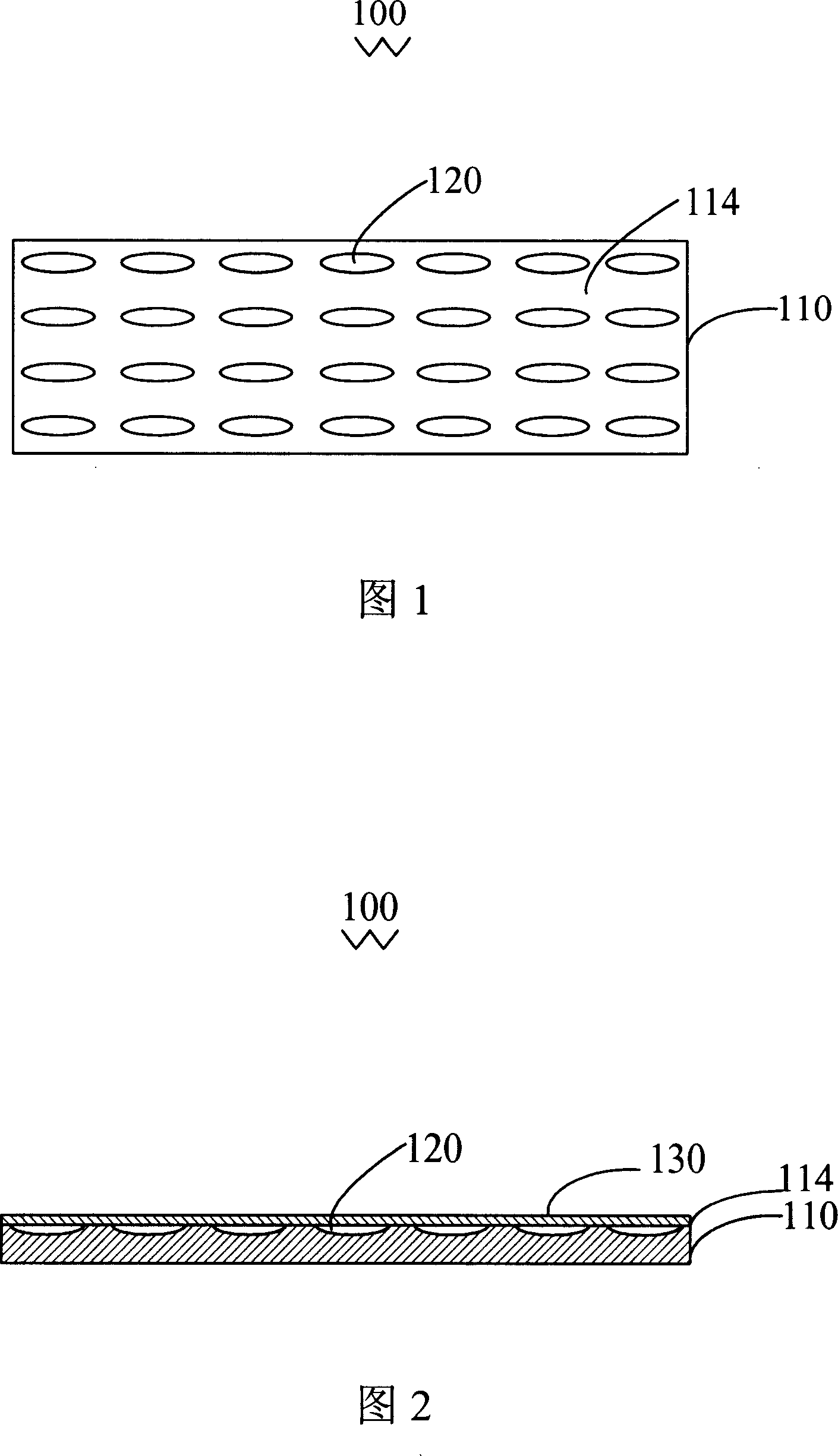
[0013] Referring to FIG. 1 , a polarizer 100 provided by an embodiment of the present invention includes a transparent substrate 110 having a light incident surface 112 and a light exit surface 114 . The light-emitting surface 114 has several grooves 120 with long and short axes, the short-axis dimensions of the several grooves 120 are smaller than the central wavelength of the incident light, and the long-axis dimensions of the several grooves 120 are equal to or greater than the incident light. The central wavelength of the light, and the long axis is parallel to the light emitting surface 114 .

[0014] The transparent substrate 110 is made of a material with optical anisotropy, and the transparent substrate 110 can at least allow visible light (the central wavelength range is about 390 nm to 780 nm) to pass through. In this embodiment,...


PUM

PropertyMeasurementUnit
thicknessaaaaaaaaaa
depthaaaaaaaaaa
thicknessaaaaaaaaaa

Abstract

The invention relates to a diffuser, including a transparent substrate, a light incoming surface and a light reflecting surface arranged on the transparent substrate. The light incoming surface is in parallel with the light output surface. The material of the transparent substrate is anisotropic. The light output surface is provided with a plurality of grooves with long and short shafts; the size of the short shaft of the grooves is smaller than the central wavelength of the incoming light; the size of the long shaft of the grooves is equal to or larger than the central wavelength of the incoming light; and the long shaft is in parallel with the light reflecting surface. The invention also relates to a LCD device by using the diffuser. The diffuser has good scattering performance and the adoption of the diffuser can obtain a high-brightness LCD, thus effectively improving the light utilization.

Description

technical field [0001] The invention relates to a polarizer and a liquid crystal display device using the polarizer. Background technique [0002] In recent years, liquid crystal display devices have been widely used in modern information equipment such as notebook computers, mobile phones, and personal digital assistants due to their lightness, thinness, and low power consumption. The liquid crystal display device is a passive component, which cannot emit light by itself, and requires a light source system as a light source for the liquid crystal display device, such as a backlight system. A common backlight system includes a light guide plate and a light source. The light emitted from the backlight system must be polarized when it enters the liquid crystal cell, so it is usually necessary to attach polarizers on both sides of the liquid crystal cell to integrate the polarization state of the liquid crystal. [0003] Existing polarizers include absorbing polarizers and re...

Claims


Application Information

Patent Timeline
Patent Type & Authority Applications(China)
IPC IPC(8): G02B5/30G02B1/00G02F1/1335
CPCG02F1/133528G02B5/3083
Inventor 陈杰良
Owner HONG FU JIN PRECISION IND (SHENZHEN) CO LTD
Why Eureka
Try Eureka