Eureka AIR delivers breakthrough ideas for toughest innovation challenges, trusted by R&D personnel around the world.

Film feeding mechanism for film type camera

A film conveying mechanism and film technology, applied in the field of film conveying mechanism, can solve the problems such as the difficulty of film conveying in the same amount as the camera shooting cycle, and achieve the effects of compact structure, large transmission torque and high reliability

Inactive Publication Date: 2008-02-13
CHANGCHUN INST OF OPTICS FINE MECHANICS & PHYSICS CHINESE ACAD OF SCI
View PDF0 Cites 0 Cited by
  • Summary
  • Abstract
  • Description
  • Claims
  • Application Information

AI Technical Summary

Problems solved by technology

The traditional film-type aerial camera equal-quantity film feeding technology mostly uses the method of directly driving the film roller to rotate by the stepping motor, and realizes the equal-quantity film feeding of the camera by controlling the stepping motor rotation angle. This method is often limited by the structural size of the motor, Due to the limitation of torque and rotational speed, it is difficult to achieve the same amount of film delivery by using a stepping motor to directly drive the film roller to rotate when the camera photo period is short and the imaging format is large.

Method used


Image

  • Film feeding mechanism for film type camera

Examples


Embodiment approach

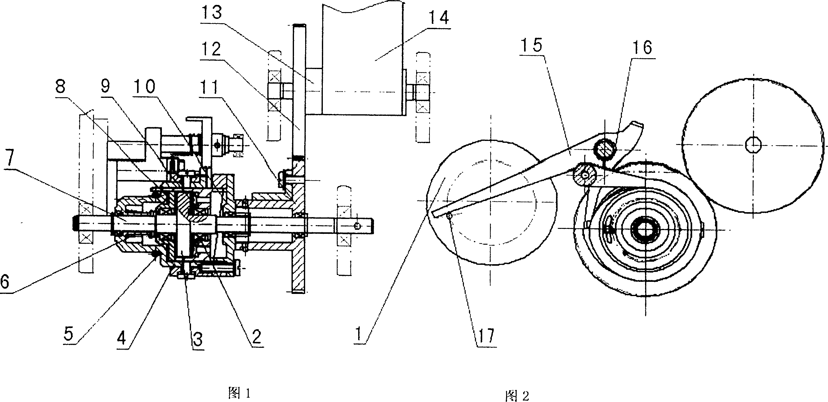
[0018] One week electromagnetic coil 1, transmission shaft 7, A gear 11, B gear 12, measuring sheet roller 13, stop hook 15 are respectively fixed on the support frame structure by bearing 2.

[0019] A transmission friction disc 3, a clutch housing 4, a transition piece 8, B transmission friction disc 9, C transmission friction disc 10, and A gear 11 are respectively installed on the transmission shaft 7 through the bearing 2.

[0020] Stop the long handle of hook 15 and contact with the dial pin 17 on the electromagnetic coil 1 of a week, stop the breach contacting with the flange on the clutch housing 4 of a week, and stop the clutch housing 4 rotations of a week.

[0021] Stop hook spring 16 one end links to each other with stop hook 15, and the other end is fixed on the support frame, and is wound on the stop hook 15, guarantees that the long handle of stop hook 15 leans against on the dial pin on the week electromagnetic coil 1 all the time. When one week electromagnetic...


PUM


Abstract

The invention discloses a film camera transport mechanism, pertaining to a camera structure and design. The invention changes the mode that the electromagnet directly controls the separation and joint of the friction film, adopts the torque motor instead of the stepper motor and achieves the equivalent film transport of camera through the structure of sheet roll rotation through a periclutch drive. The mechanism includes an electromagnetic coil, a bearing, an A transmission friction disc, a periclutch shell, a drive spring, a separation spring, a transmission shaft, a transition element, a B transmission friction disc, a C transmission friction disc, an A gear, a B gear, a sheet roll, a film, a stop hook, a stop hook spring and a pin. The film transport mechanism has the advantages of compact structure, large transmission torque, high reliability, rapid transport speed and easy control of the circuit, which can solve the problems of film camera such as short shooting period and large imaging format. With small difficulty in processing, the mechanism can be also applied in the fields of printing and textile through appropriate improvement, so that the invention has a wide ranged of application.

Description

technical field [0001] The invention relates to a film conveying mechanism for a film camera, which belongs to the structural design of the camera, and particularly relates to the improvement of the film conveying mechanism of the film camera. Background technique [0002] Equal film feeding technology is one of the key technologies of film-type aerial cameras. The traditional film-type aerial camera equal-quantity film feeding technology mostly uses the method of directly driving the film roller to rotate by the stepping motor, and realizes the equal-quantity film feeding of the camera by controlling the stepping motor rotation angle. This method is often limited by the structural size of the motor, Due to the limitation of torque and rotational speed, it is difficult to achieve equal film delivery by using a stepping motor to directly drive the film roller to rotate when the camera has a short photographing cycle and a large imaging format. Contents of the invention [...

Claims


Application Information

Patent Timeline
IPC IPC(8): G03B1/20
Inventor 张洪文丁亚林张继超
Owner CHANGCHUN INST OF OPTICS FINE MECHANICS & PHYSICS CHINESE ACAD OF SCI
Why Eureka
Eureka Blog
Learn More