Testing structure for MOS capacitor and location method for failure point

A technology of capacitance testing and positioning method, which is applied in the direction of electronic circuit testing, non-contact circuit testing, semiconductor/solid-state device testing/measurement, etc., can solve the problems of labor-intensive, cost-increased, time-consuming, etc., and achieve simple manufacturing process and increase Production cost, the effect of avoiding repeated cutting

Inactive Publication Date: 2008-02-13
SEMICON MFG INT (SHANGHAI) CORP +1
View PDF1 Cites 24 Cited by
  • Summary
  • Abstract
  • Description
  • Claims
  • Application Information

AI Technical Summary

Problems solved by technology

Although the photoelectric test structure can be used to assist in the location of failure points, the composition of the photoelectric test structure is too complex, and the appl

Method used


Image

  • Testing structure for MOS capacitor and location method for failure point
  • Testing structure for MOS capacitor and location method for failure point
  • Testing structure for MOS capacitor and location method for failure point

Examples


no. 1 example

[0044] As the first embodiment illustrating the method of the present invention, the specific implementation steps of applying the method of the present invention to locate the failure point and perform failure analysis are:

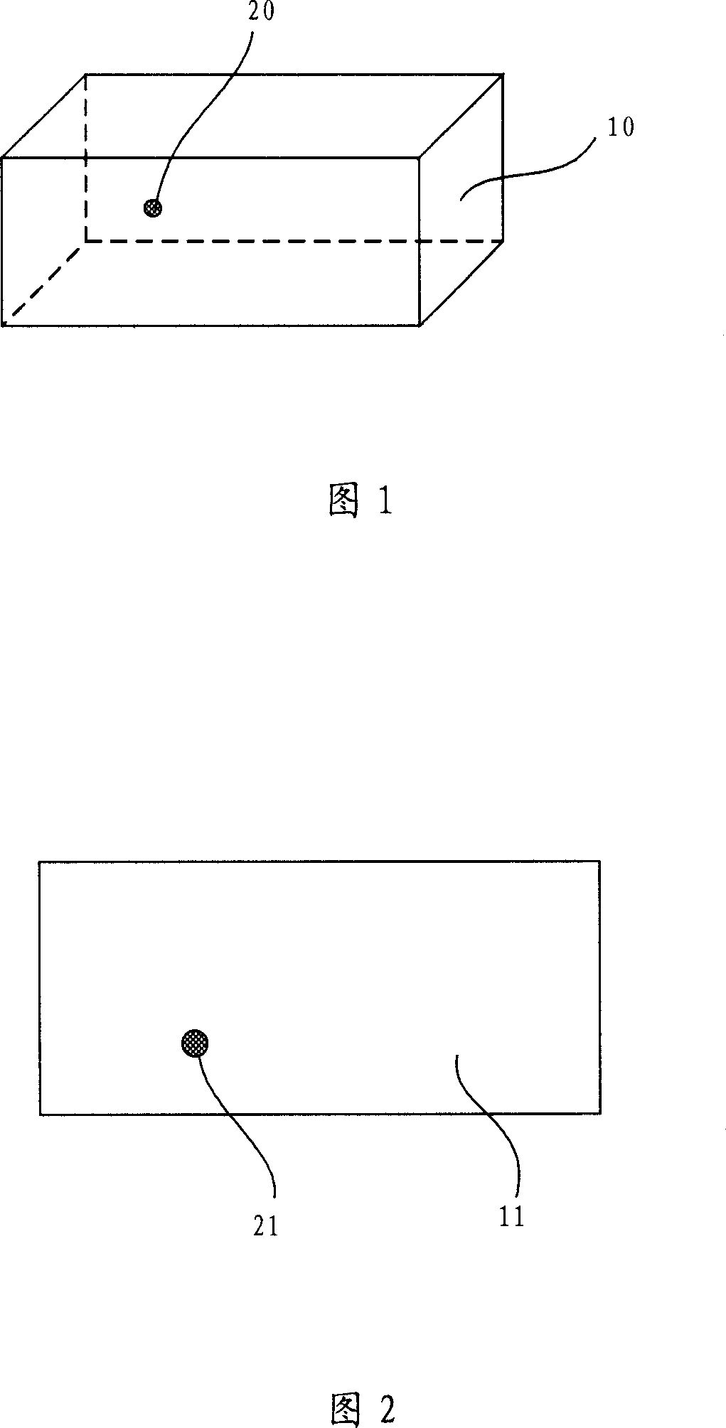
[0045] First, a test MOS capacitor is formed.

[0046] The test MOS capacitor is formed simultaneously with the normal product and has the same structure; the test MOS capacitor is formed on the dicing line in the wafer; for the convenience of failure point detection, the test MOS capacitor grid size can be designed to be large enough, as the method of the present invention In an embodiment, the gate size of the test MOS capacitor is selected as: 50 microns*50 microns.

[0047] Admittedly, the determination of the gate size of the test MOS capacitor is a special choice made for the convenience of describing the specific embodiments of the present invention, and should not be used as a limitation to the implementation of the method of the present inventio...

no. 2 example

[0064] As the second embodiment of the present invention, the specific implementation steps of applying the method of the present invention to locate the failure point and perform failure analysis are as follows:

[0065] First, a test MOS capacitor is formed.

[0066] The test MOS capacitor is formed simultaneously with the normal product and has the same structure; the test MOS capacitor is formed on the dicing line in the wafer; for the convenience of failure point detection, the test MOS capacitor grid size can be designed to be large enough, as the method of the present invention In an embodiment, the gate size of the test MOS capacitor is selected as: 50 microns*50 microns.


PUM


Abstract

A method of MOS capacitance invalidation point fixation comprises: a measuring MOS capacitance is formed; a medium layer and a metal layer are deposited on the top of the MOS capacitance and a MOS capacitance measuring structure is obtained; the MOS capacitance measuring structure is measured and invalidation point position information is obtained. The method of depositing the metal layer on the top of the measuring MOS capacitance comprises depositing a first assisting metal layer and a second assisting metal layer or depositing a metal layer, having regular figures, on the top of the measuring MOS capacitance. A reseau formed by double-level metal wire or regular figure in the single-layer metal layer is used as coordinates of the optical detection figure, thus providing exact invalidation point position information. The manufacturing processes of the regular figures in the double-layer metal wire or the single-layer metal layer are simple and do not separately need to add production steps or lead in new materials. The method neither increases the production cost nor has bad influences on the properties of the devices obtained finally.

Description

technical field [0001] The invention relates to the technical field of semiconductor manufacturing, in particular to a MOS capacitor testing structure and a failure point location method. Background technique [0002] At present, Metal-Oxide-Semiconductor Field Effect Translator (MOSFET), as a voltage control device, is widely used in various electronic circuits. The middle part of the MOSFET is a MOS capacitor composed of metal-oxide-semiconductor. The oxide layer acts as an insulation between the metal and the semiconductor; the metal layer on the oxide layer is used as the gate of the MOSFET. In the current process, polysilicon or polysilicon and metal are mostly used. The combination of silicide replaces the metal material; the semiconductor under the oxide layer is the substrate, and the source and drain of the MOSFET are formed in it; applying a voltage between the gate of the MOS capacitor and the substrate can change the electric field in the oxide layer Intensity, ...

Claims


Application Information

Patent Timeline
IPC IPC(8): H01L23/544H01L21/66G01R31/308
CPCH01L2924/0002
Inventor 孙艳辉郭廓
Owner SEMICON MFG INT (SHANGHAI) CORP
Why Eureka
Try Eureka