

Hydraulic shovel
A technology for hydraulic excavators and hydraulic pumps, which is applied to earth moving machines/shovels, mechanical equipment, fluid pressure actuators, etc., and can solve the problem of poor initial response of hydraulic excavators, inability to ensure necessary hydraulic pressure, and failure to perform Problems such as component work, to achieve the effect of good start-up, simple structure, and high degree of design freedom
- Summary
- Abstract
- Description
- Claims
- Application Information
AI Technical Summary
Problems solved by technology
Method used
Image

Examples
no. 1 approach
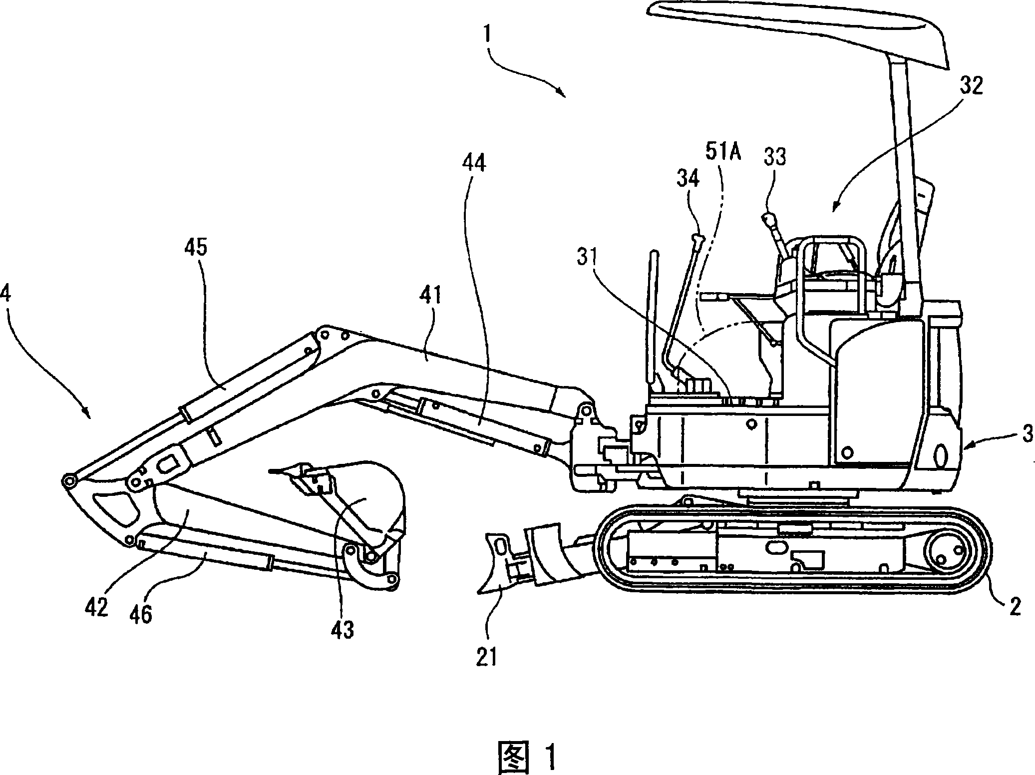
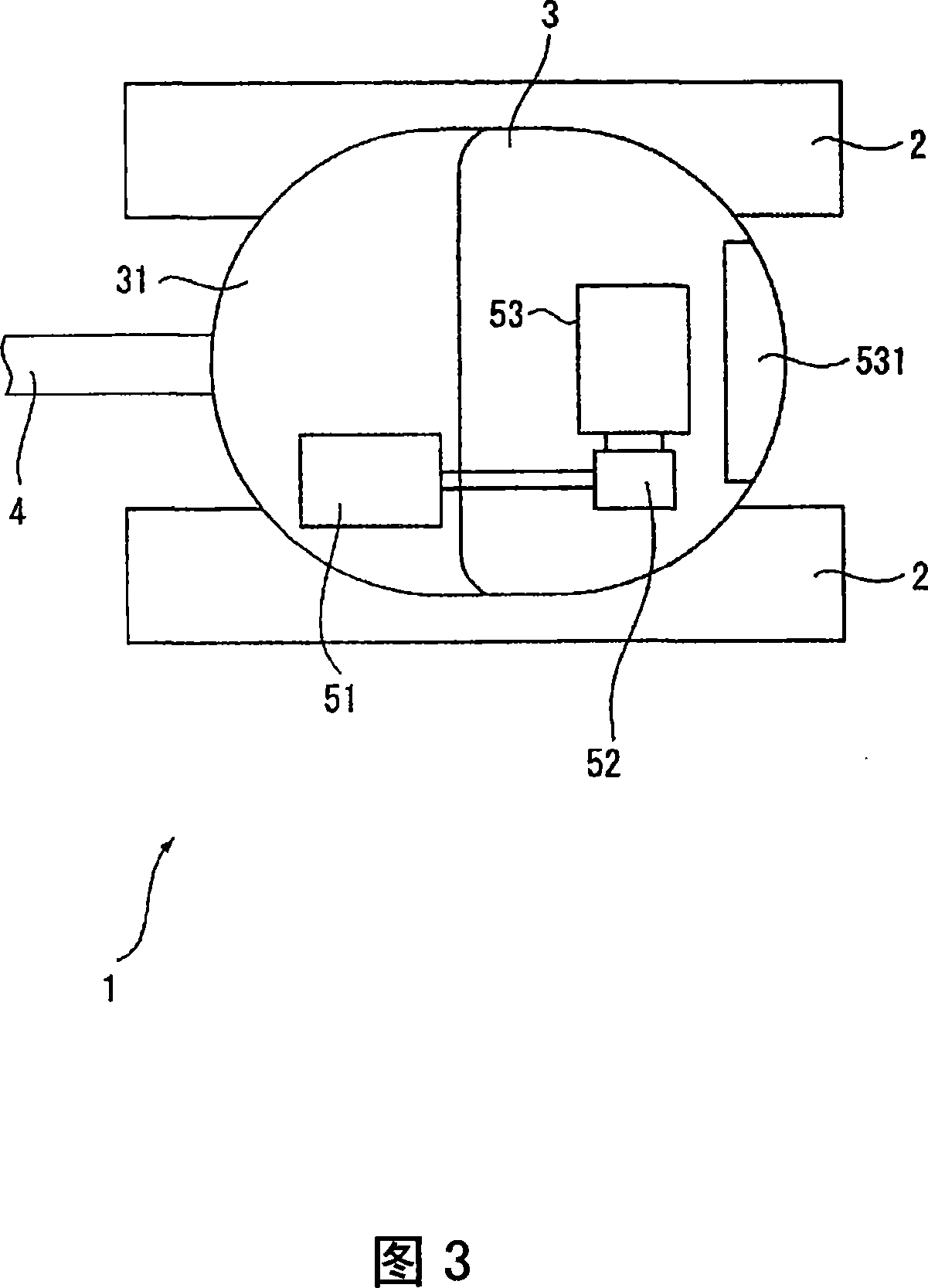
[0034] FIG. 1 shows an overall view of a hydraulic excavator 1 according to a first embodiment of the present invention. In FIG. 1 , a hydraulic excavator 1 includes: a running body 2 ; a rotatable swing body 3 arranged above the running body 2 ; and a working machine 4 mounted in front of the swing body 3 .
[0035] Although the running body 2 adopts a crawler-type running body equipped with crawlers in this embodiment, it is not limited to this, and for example, a wheel-type running body equipped with tires or another suitable type of running body may be used. A bulldozer 21 is provided in front of the traveling body 2 .
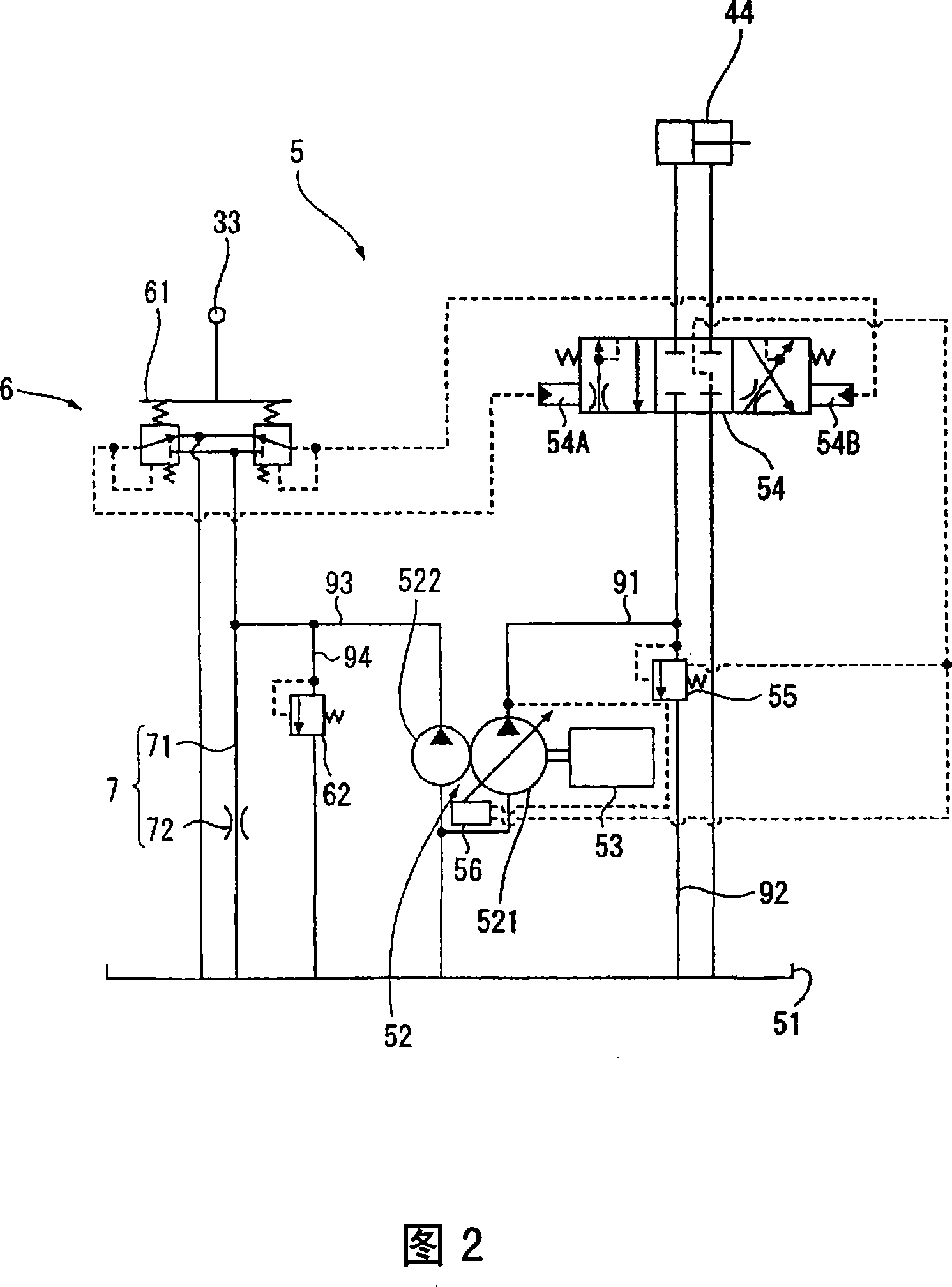
[0036] A driver's seat 32 is provided above the revolving body 3 , and the operation of the working machine 4 , the rotating motion of the revolving body 3 , and the left and right running motion of the traveling body 2 can be operated through the working machine control lever 33 and the traveling control lever 34 . In addition, a hydraulic circuit 5 (see...
no. 2 approach
[0062] Next, a second embodiment of the present invention will be described. The structure of the second embodiment is the same as that of the first embodiment except that the installation position of the pipeline with a throttle valve 7 is different from that of the first embodiment.
[0063] FIG. 5 is a diagram showing a hydraulic circuit 5 of a hydraulic excavator 1 according to a second embodiment of the present invention. In this FIG. 5 , the line 7 with a throttle valve is provided on the line 91 near the control valve 54 downstream of the unloading valve 55 (ie, between the unloading valve 55 and the control valve 54 ).
[0064] In such a second embodiment, when air is mixed between hydraulic oil tank 51 and hydraulic pump 52 , when hydraulic pump 52 operates, air is discharged from main pump 521 to hydraulic oil tank 51 through throttle line 7 . Since the pipeline 7 with a throttle valve is provided on the side of the main pump 521 whose flow rate is larger than that ...
no. 3 approach
[0067] Next, a third embodiment of the present invention will be described. The third embodiment differs from the first embodiment in that the line with a switching valve 8 is provided instead of the line with a throttle valve 7 , but the structure is the same as that of the first embodiment.
[0068]FIG. 6 is a diagram showing a hydraulic circuit 5 of a hydraulic excavator 1 according to a third embodiment of the present invention. In this FIG. 6 , in the pipeline 93 , in the vicinity of the PPC valve 61 downstream of the safety valve 62 (that is, between the safety valve 62 and the PPC valve 61 ), a pipeline 81 communicating the pipeline 93 with the working oil tank 51 is provided. , and a switching valve 82 that is provided in the middle of the pipeline 81 and can open and close the flow path of the pipeline 81 . The switching valve 82 can be manually switched by an operator at the driver's seat 32 . Furthermore, these piping 81 and switching valve 82 are provided, and th...
PUM
 Abstract
Description
Claims
Application Information