Automobile body rear floor device

A rear floor and floor technology, applied in vehicle parts, transportation and packaging, superstructure, etc., can solve the problems of high use cost, insufficient rigidity, increased fuel consumption, etc., to reduce maintenance costs, mature production technology, and increase internal space. Effect

Inactive Publication Date: 2008-02-20
SHANGHAI HUAPU AUTOMOBILE CO LTD
View PDF0 Cites 5 Cited by
  • Summary
  • Abstract
  • Description
  • Claims
  • Application Information

AI Technical Summary

Problems solved by technology

In the past, the design of the rear floor of the car body was often insufficient in rigidity. When the car was in the process of a rear collision, such as a large impact force, the rear part of the car body absorbed the impact energy and deformed excessively. The deformed car body directly squeezed the fuel tank, causing the fuel tank to be damaged. damage, which can easily cause danger and threaten the safety of passengers; if the impact force of the collision is small, because the rear floor of the vehicle body lacks the necessary rigidity and strength, it will cause permanent damage to the vehicle body and damage the interests of consumers
[0004] In response to this situation, when designing and producing automobiles, most automobile manufacturers currently adopt the solution of setting many beams and longitudinal beams with complex shapes on the floor and adding reinforcement parts, and some use very thick steel plates, or use Various forms of high-strength steel plates and other solutions, but these solutions have great limitations in practical applications: when the car has a rear impact with a large impact, the rear of the body is too rigid because the body cannot Absorb huge impact energy through deformation, and give passengers a huge impact, endangering the personal safety of passengers
[0005] In these solutions, there are still disadvantages such as difficult part forming, complex production process, high part scrap rate, high production cost, etc.
[0006] When consumers use the car with the above-mentioned design scheme on the rear floor of the body, the fuel consumption is increased and the use cost is relatively high because the weight of the body cannot be effectively controlled.

Method used


Image

  • Automobile body rear floor device
  • Automobile body rear floor device
  • Automobile body rear floor device

Examples


Embodiment Construction

[0033] In order to make the above objects, features and advantages of the present invention more comprehensible, the present invention will be further described in detail below in conjunction with the accompanying drawings and specific embodiments.

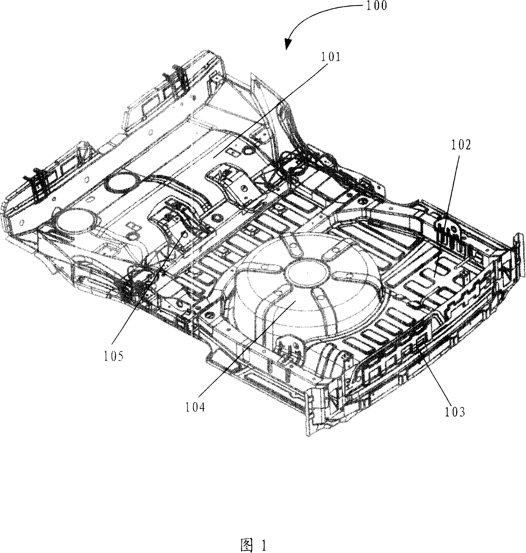
[0034] Please refer to FIG. 1 , which is a structural schematic diagram of a vehicle body rear floor device 100 according to the present invention. The vehicle body rear floor device 100 includes a rear floor front panel assembly 101 , a rear floor rear panel assembly 102 , a rear wall assembly 103 , Spare tire box assembly 104 and rear floor frame assembly 105, rear floor front panel assembly 101, rear floor rear panel assembly 102, rear wall assembly 103 and spare wheel box assembly 104 are welded and assembled on the rear floor frame Assembly 105 on.

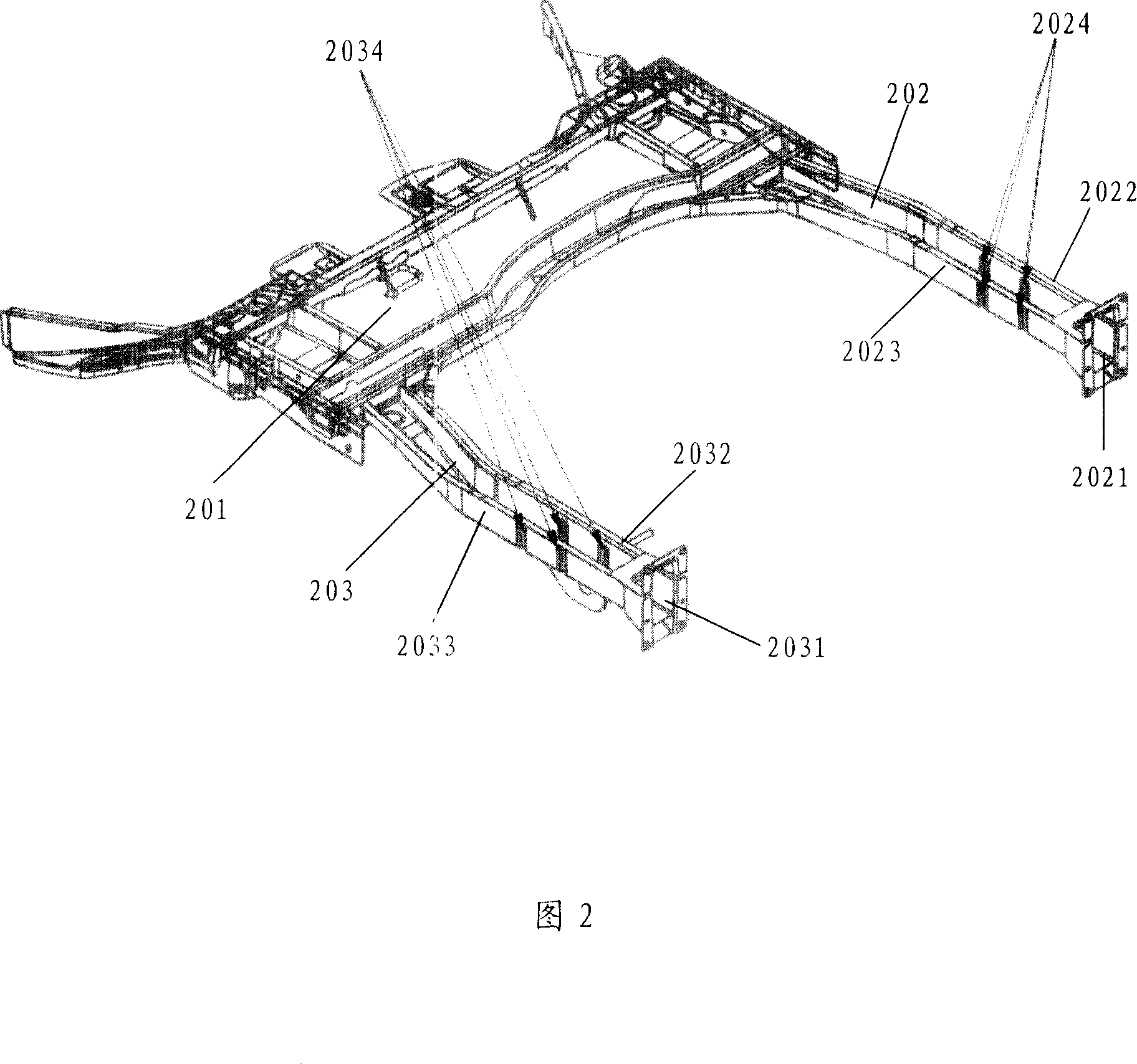
[0035] Please refer to FIG. 2 , which is a schematic structural diagram of the rear floor frame assembly 105 of the present invention. The rear floor frame assembly 105 includes ...


PUM


Abstract

The invention discloses a car body rear floor board device, comprising a rear floor board foreside panel assembly, a rear floor board rearward panel assembly, a rear wall assembly, a spare wheel case assembly and a rear floor board frame assembly, wherein, the rear floor board foreside panel assembly, the rear floor board rearward panel assembly, the rear wall assembly, and the spare wheel case assembly are combined on the rear floor board frame assembly; the left and the right longitudinal beams of the rear floor board frame assembly are respectively provided with a buffering structure which is a groove. The rear floor board rearward panel assembly comprises a first main board, a second main board and a third main board; wherein, the third main board retreats downwards relative to the first and the second main boards. The invention improves the safety of the car when rear collision happens and effectively reduces the production and use cost of the car.

Description

technical field [0001] The invention relates to the field of automobiles, in particular to a vehicle body rear floor device. Background technique [0002] As a durable consumer product, cars have gradually entered ordinary households. In recent years, the number of cars in China has grown rapidly, and traffic accidents have also increased steadily. In order to protect the safety of passengers in the after-collision of automobiles, my country began to implement new fuel leakage standards for after-collisions on July 1, 2006, and put forward requirements for the safety performance of automobiles in after-collisions. When consumers buy a car, the safety of the car has become one of the most important points for consumers. Therefore, it is necessary to optimize the body structure design and improve the active safety of the body design to adapt to new collision regulations and meet consumer demand. [0003] In the design of the body structure, the design of the rear floor of th...

Claims


Application Information

Patent Timeline
Patent Type & Authority Applications(China)
IPC IPC(8): B62D25/20
Inventor 屠振涛狄成林白昆程张东学
Owner SHANGHAI HUAPU AUTOMOBILE CO LTD
Why Eureka
Try Eureka