
Ignition device for an internal combustion engine and method for its operation

一种点火装置、内燃机的技术,应用在发动机点火、电火花点火控制器、特定发动机的发电机等方向,能够解决加强气缸热负荷等问题,达到精确点火、简化机械结构的效果

Active Publication Date: 2008-02-20
ANDREAS STIHL AG & CO KG
View PDF0 Cites 6 Cited by
  • Summary
  • Abstract
  • Description
  • Claims
  • Application Information

AI Technical Summary

Problems solved by technology

This can cause cooling problems, thus greatly intensifying the thermal load on the cylinder

Method used


Image

  • Ignition device for an internal combustion engine and method for its operation
  • Ignition device for an internal combustion engine and method for its operation
  • Ignition device for an internal combustion engine and method for its operation

Examples


Embodiment Construction

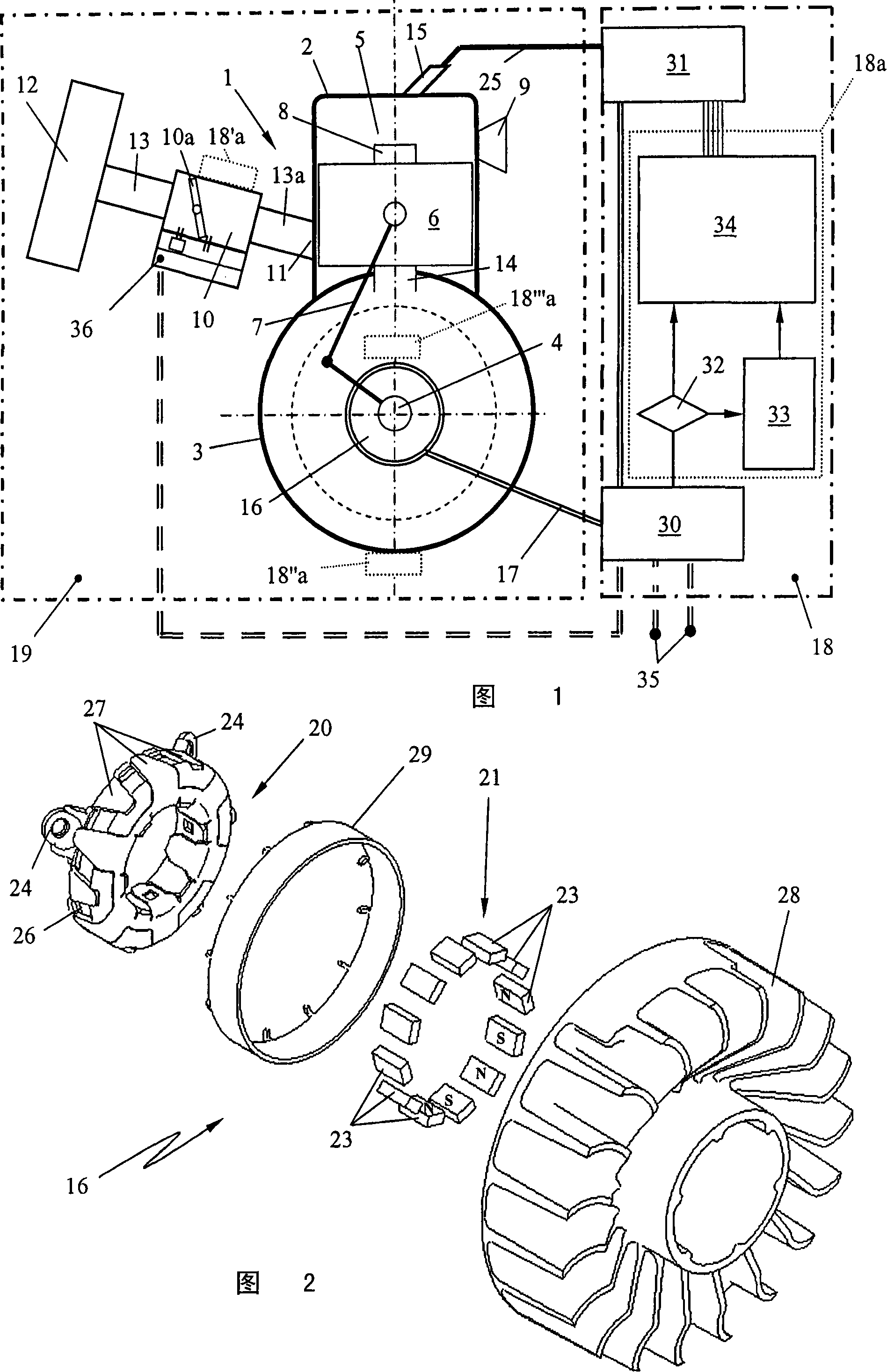
[0035] In the schematic diagram of FIG. 1 , the engine unit 19 includes an internal combustion engine 1 , which is designed in particular as a two-stroke engine. The ignition device according to the invention is not restricted to use in single-cylinder or multi-cylinder two-stroke engines, it can also be used in single-cylinder or multi-cylinder four-stroke engines or similar engines, in particular reciprocating piston engines.

[0036] The internal combustion engine 1 of the engine unit 19 encloses a cylinder 2 with a crankcase 3 in which a crankshaft 4 is rotatably mounted. A combustion chamber 5 is formed in the cylinder 2 and is delimited by a piston 6 moving up and down. The piston 6 is connected with the crankshaft 4 in the crankcase 3 through the connecting rod 7 and pushes the crankshaft 4 to rotate. In the shown embodiment, an inlet window 8 for combustion air and / or mixture opens into the combustion chamber 5, wherein the inlet window 8 is arranged at the end of an ...


PUM


Abstract

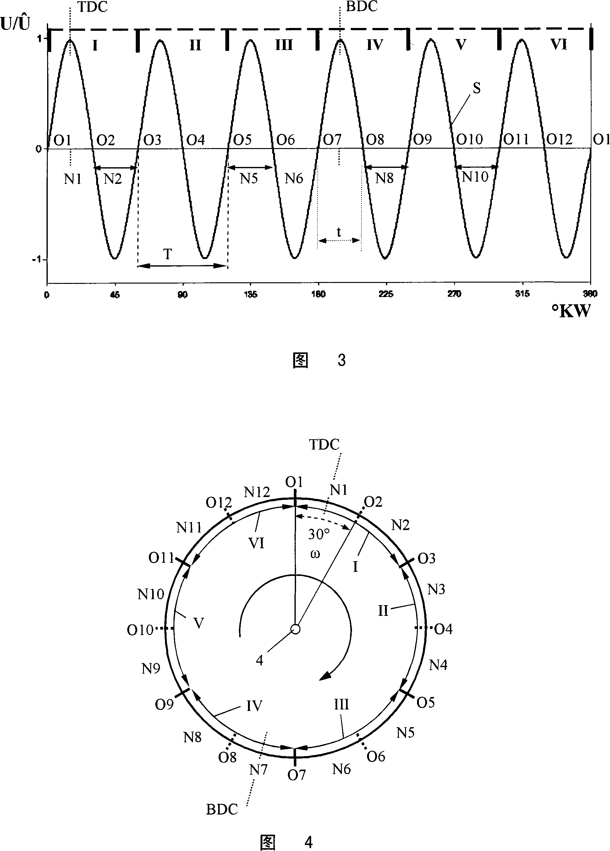
The invention relates to an ignition device for a motor unit (19) with an internal combustion engine (1) in hand-held working apparatus, wherein the internal combustion engine (1) is provided with a piston (6), a combustion chamber (5) with a spark plug (15) and a crankshaft (4) driven by the piston (6). A signal generator (16) is driven by the crankshaft (4) and emitts for one crankshaft revolution an alternating voltage signal (S) to an ignition unit (18) that triggers a spark at the spark plug (15). The alternating voltage signal (S) of signal generator (16) is supplied to the ignition unit as an information signal sufficient for operating the internal combustion engine (1). And an angle information signal is conformed in one unit (30), the angle information signal is evaluated to accurately correspond with the rotation position of machinery crankshaft angle position.

Description

technical field [0001] The invention relates to an ignition device for an engine unit with an internal combustion engine, in particular an ignition device for an engine unit with a two-stroke engine in a portable hand-held power tool. Background technique [0002] Modern internal combustion engines are controlled by ignition devices, such as those used in hand-held portable work tools such as motor chainsaws, free cutters, split grinders, air blowers or similar appliances. The ignition device is used in addition to supplying high voltage to the spark plug. There must be an ignition sensor outside of the AC voltage signal, which can be set approximately 40° before top dead center (OT) and trigger the ignition. The ignition sensor must be rotationally fixed on the crankcase on the circumference of the running pole rotor, wherein in series production there are deviations in the mechanical arrangement of the ignition sensor which can have a negative effect on the ignition timing...

Claims


Application Information

Patent Timeline
Patent Type & Authority Applications(China)
IPC IPC(8): F02P5/15
CPCF02P1/04F02P7/0775
Inventor G·梅尔W·莱赫T·纽梅尔E·谢伯M·阿鲍-阿利
Owner ANDREAS STIHL AG & CO KG
Learn More