Device and method for initiating code chip on-board burning for processor system

A processor system and startup code technology, applied in program control devices, electrical digital data processing, program loading/starting, etc., can solve problems such as high programming cost and complicated programming process

Inactive Publication Date: 2008-02-20
BEIJING PICOHOOD TECH
View PDF2 Cites 7 Cited by
  • Summary
  • Abstract
  • Description
  • Claims
  • Application Information

AI Technical Summary

Problems solved by technology

[0006] The technical problem to be solved by the present invention is to provide a device and method for realizing BOOTROM on-board programming of a pr

Method used


Image

  • Device and method for initiating code chip on-board burning for processor system
  • Device and method for initiating code chip on-board burning for processor system
  • Device and method for initiating code chip on-board burning for processor system

Examples


Embodiment Construction

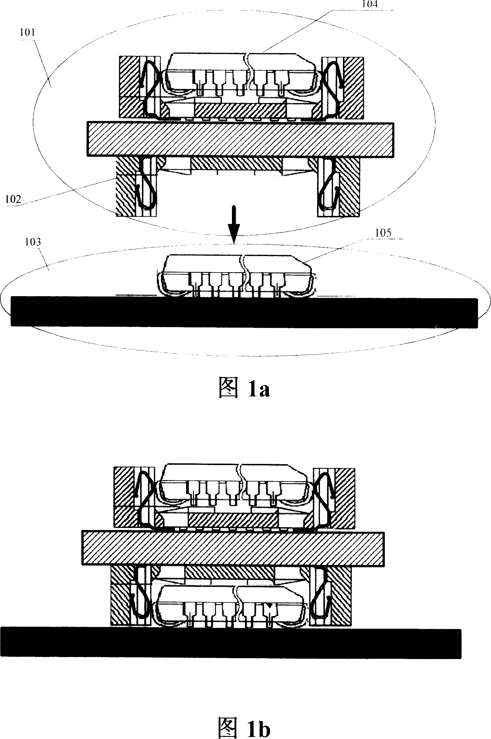
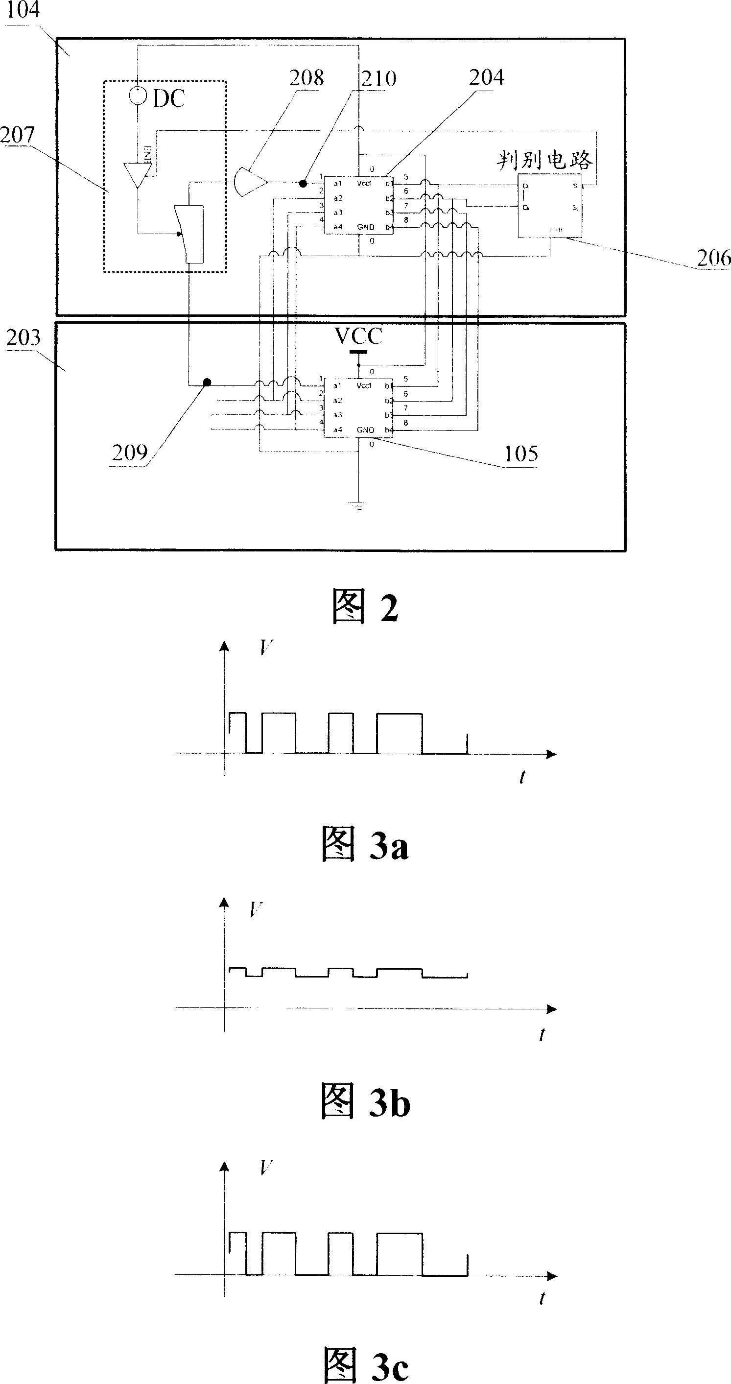
[0047] The burning device of the present invention is shown in FIG. 1 a , the burning device 101 includes a burning circuit 104 and a burning jig 102 . The burning circuit 104 is a BOOTROM that has been burned outside the board, and the target circuit 105 is the BOOTROM that needs to be burned in the target system 103 . The programming circuit 104 and the target circuit 105 are fixedly connected to the programming target single board by the programming jig 102 , and the programming target single board loaded with the programming device 101 is shown in FIG. 1 b . The models of the programming circuit 104 and the target circuit 105 are exactly the same or the circuit parameters are consistent, and the pins of the two BOOTROMs correspond one to one. In order to prevent bus conflicts when the two BOOTROMs are accessed by the processor, the control signals (such as CS chip select signals) of the two BOOTROMs need to be processed separately, that is, to ensure that the two BOOTROMs ...


PUM


Abstract

The utility model discloses a method of achieving on-board imprinting of the processor system BOOTROM; wherein, the steps comprise: connecting the imprinting device with an imprinting circuit with the imprinting jig to the target circuit on the imprinting target single board; enabling the replacement circuit of the imprinting circuit while disenabling the target circuit through switching the circuit; the target system starting from the replacement circuit, enabling the target circuit while disenabling the replacement circuit through switching the circuit; the target system reading the imprinting mapping into the target circuit. The method of the utility model can remove the jack of BOOTROM directly and achieve the BOOTROM on-board imprinting after the inserted BOOTROM is welded to the single board directly, which has the advantages of not changing the original design, not adding the design cost of the software and hardware of the single board, and having easy operation.

Description

technical field [0001] The invention relates to a device and a method for burning a boot code chip (BOOTROM) of a processor system, in particular to a device and a method for burning a BOOTROM on a board. Background technique [0002] Existing processor systems all have a BOOTROM for storing startup programs. Usually, the BOOTROM selects a low-cost plug-in flash memory (FLASH) chip, burns the startup program into the FLASH through the burner, and then inserts the FLASH into the corresponding socket of the single board as the BOOTROM of the processor. [0003] During production, processing, transportation, and use, problems such as damage to the BOOTROM socket and poor contact of the BOOTROM often occur due to the socket, so removing the BOOTROM socket and directly soldering the BOOTROM to the board has become a requirement. However, if you remove the BOOTROM socket, you will face the problem of how to burn the BOOTROM on the board. [0004] In the Chinese patent 02125596.2...

Claims


Application Information

Patent Timeline
IPC IPC(8): G06F13/00G06F9/445
Inventor 宋臻宇张加民
Owner BEIJING PICOHOOD TECH
Why Eureka
Try Eureka