Antenna device and portable wireless device

A kind of radio equipment, portable technology, applied in antenna support/installation device, device that enables antenna to work in different bands at the same time, antenna, etc., can solve the problems of antenna performance degradation, length increase, design performance deterioration, etc., to achieve The effect of preventing the degradation of antenna performance

Inactive Publication Date: 2008-02-20
PANASONIC CORP
View PDF1 Cites 0 Cited by
  • Summary
  • Abstract
  • Description
  • Claims
  • Application Information

AI Technical Summary

Problems solved by technology

[0008] In the existing portable radio equipment shown in Fig. 10 and Fig. 12, in order to make the electronic parts 10 containing metal as the close object in the second casing 3 not to be separated from the monopole antenna 6 in Fig. 10 and the one in Fig. 12 when it is closed Components 11 and 13 are close to reduce the performance of the antenna. As shown in Figure 11 and Figure 13, it is necessary to expand the internal space of the first casing 1 for arranging components 6, 11, 12. For portable devices that require further miniaturization For radio equipment, further setting another space inside the first casing 1 will make the length of the first casing 1 longer, and the length of the first casing 1 is longer than the length of the second casing 3, because the overall length Therefore, there is not only the disadvantage of lack of portability, but also the disadvantage of poor design performance

Method used


Image

  • Antenna device and portable wireless device
  • Antenna device and portable wireless device
  • Antenna device and portable wireless device

Examples


Embodiment approach

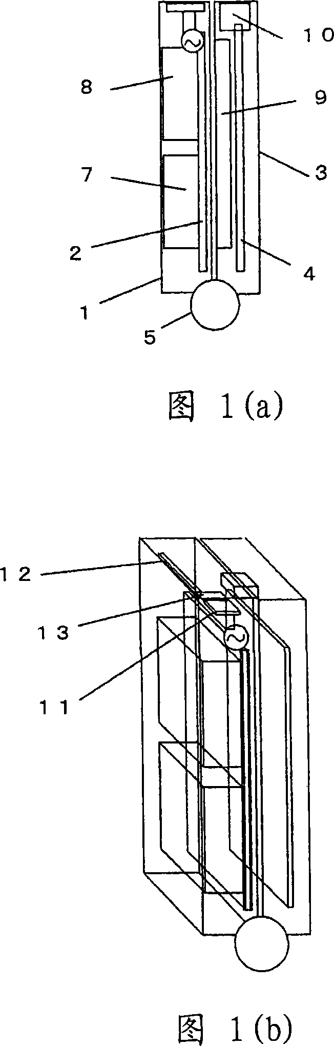
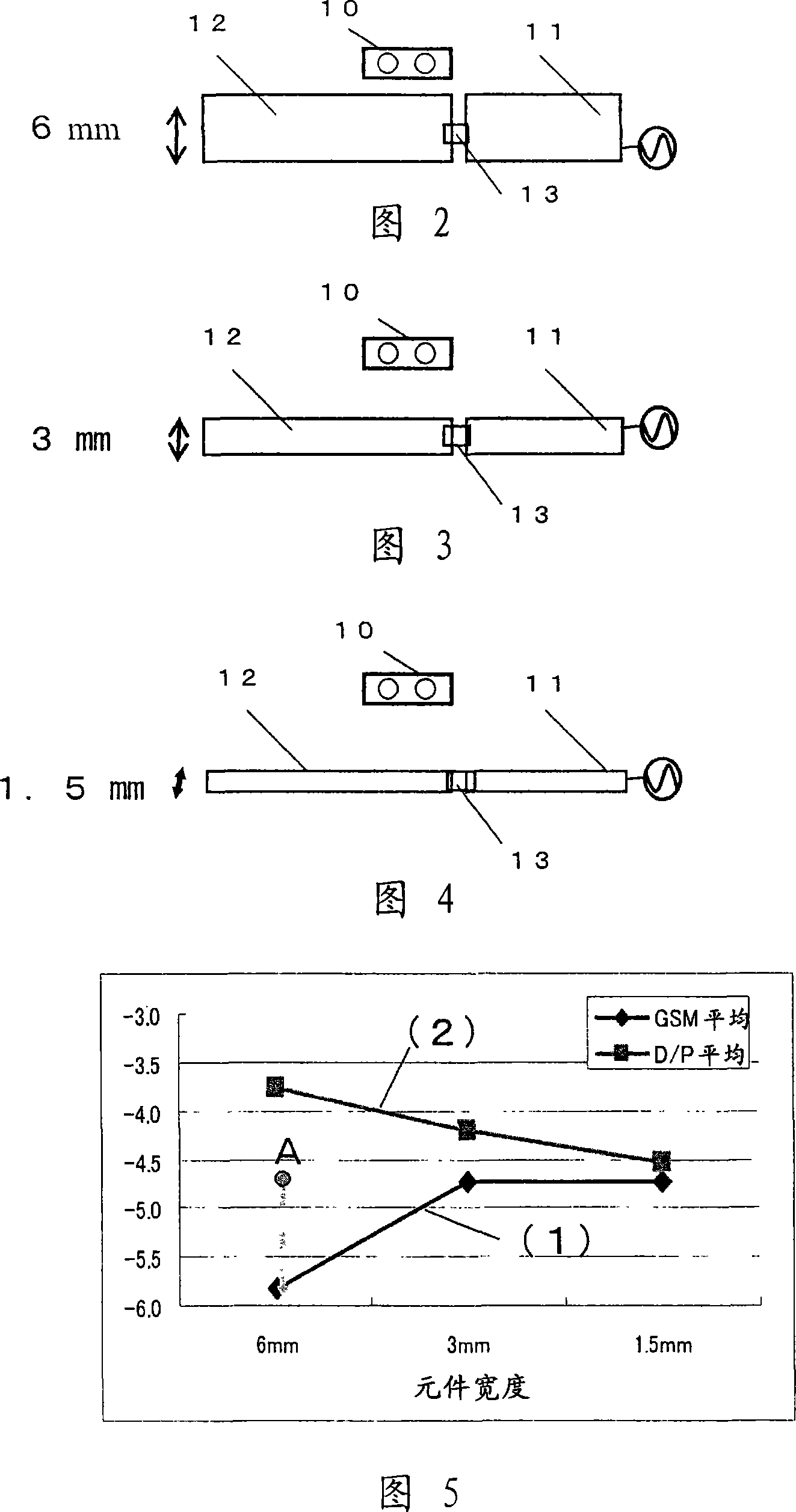
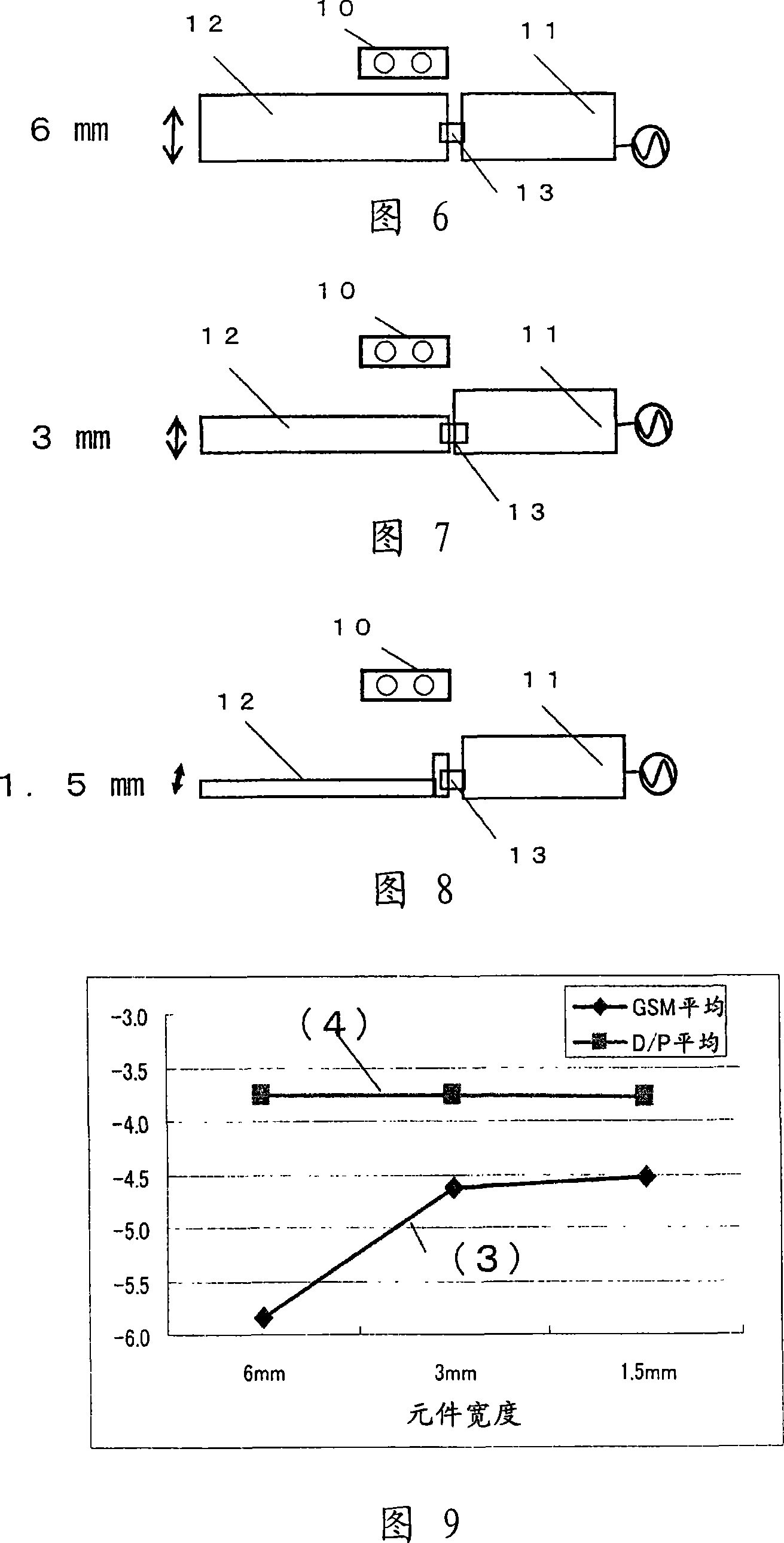
[0051] Next, the characteristics of the antennas of the portable radio equipment shown in FIG. 12 and FIG. 1 will be described based on test results. 2 is a sectional view of the structure of the antenna element in which only the antenna portion in FIG. 12 is enlarged, and when the first casing 1 and the second casing 3 are folded, when the casings are viewed from the front end direction opposite to the hinge.

[0052] The operating principle of this antenna element structure is as follows. By inserting a resonant circuit 13 that cuts off a predetermined frequency in the middle of the element, it cuts off a low frequency when operating at a high frequency such as 1.7G to 2.2GHz (second frequency band). Observed from the power supply part The length of the element is cut by the resonant circuit 13 at high frequency, and only works when the length of the element 11 is short, and resonates in 1.7G ~ 2.2GHz. Furthermore, when the resonant circuit 13 that cuts off the predetermined...


PUM


Abstract

In a portable wireless device, antenna performance is improved while storing a conductor element in a case without increasing case sizes when two cases are closed. A monopole antenna arranged inside the first case of the portable wireless device is provided with an element (11) on a power supply side, an element (12) on an open end side, and a resonance circuit (13). A width of the open end side element (12) which comes close to an electronic component (10) including a metal arranged inside the second case when the portable wireless device is folded is set smaller than a width of the open end side element (12) which does not come close to the electronic component (10).

Description

technical field [0001] Field of the Invention The present invention relates to a dual-casing portable radio equipment having two housings, and more particularly to a portable radio equipment capable of obtaining good antenna characteristics even when the two housings are closed, and an antenna device for the portable radio equipment. Background technique [0002] In the existing double-casing type portable radio equipment, an antenna made of a plate-shaped conductor is connected to the inside of the first housing on the opposite side to the hinge that connects the first housing and the second housing relatively movably. The folded structure on the end of the first circuit board. [0003] 10(a), (b) are diagrams showing the structure of such conventional portable radio equipment, and only important parts are shown here. 2 in the figure is a first circuit board arranged inside the first housing 1, and the end of the first circuit board 2 is connected to the monopole antenna 6...

Claims


Application Information

Patent Timeline
Patent Type & Authority Applications(China)
IPC IPC(8): H01Q9/30H01Q1/24H01Q5/01H04B1/38H01Q1/52H01Q5/10H01Q5/321
CPCH01Q1/243H01Q9/40H01Q5/0034H01Q5/321
Inventor 中西英夫青木贵史
Owner PANASONIC CORP
Why Eureka
Try Eureka