Optical fibre connecting mechanism

An optical fiber connection and optical fiber technology, which is applied in the field of optical fiber connection devices and optical fiber connection components, can solve the problems of high manufacturing cost, complex product structure, and unfavorable products.

Active Publication Date: 2008-02-27
NANJING HUAMAI TECH
View PDF0 Cites 8 Cited by
  • Summary
  • Abstract
  • Description
  • Claims
  • Application Information

AI Technical Summary

Problems solved by technology

Therefore, virtually increased product prices and construction costs
Although the products of some companies do not require special tools,

Method used


Image

  • Optical fibre connecting mechanism
  • Optical fibre connecting mechanism
  • Optical fibre connecting mechanism

Examples


Embodiment Construction

[0048] An optical fiber connection device and a method for using the connection device according to an embodiment of the present invention will be described below with reference to the accompanying drawings. Throughout the drawings, the same parts are denoted by the same reference numerals.

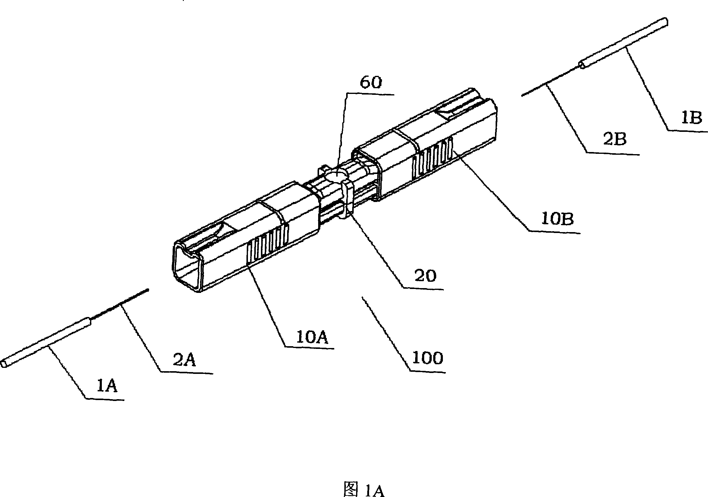
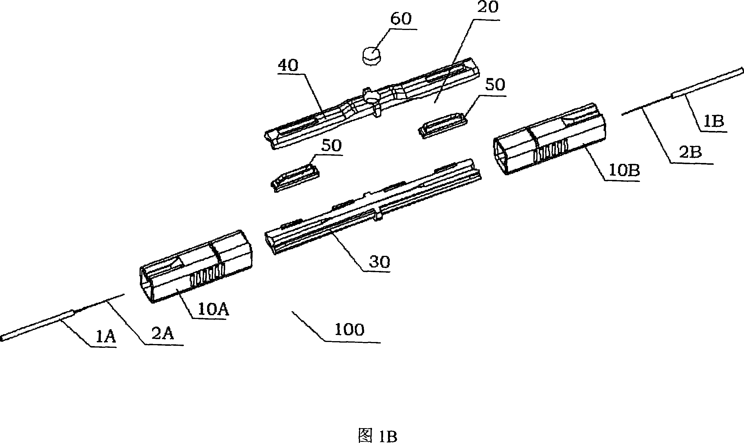
[0049] As shown in FIGS. 1A and 1B , the optical fiber connection device 100 is provided with a joint member 20 , a housing 10 , and a magnifying lens 60 . Optical fibers 1A and 1B are inserted from both ends of the connector as shown. Before the optical fiber 1 is inserted, a special tool should be used to remove the buffer coating of the optical fiber 1 for a specific length, so as to expose the bare optical fibers 1A and 1B, and then cut the bare optical fibers 1A and 1B to retain a certain length.

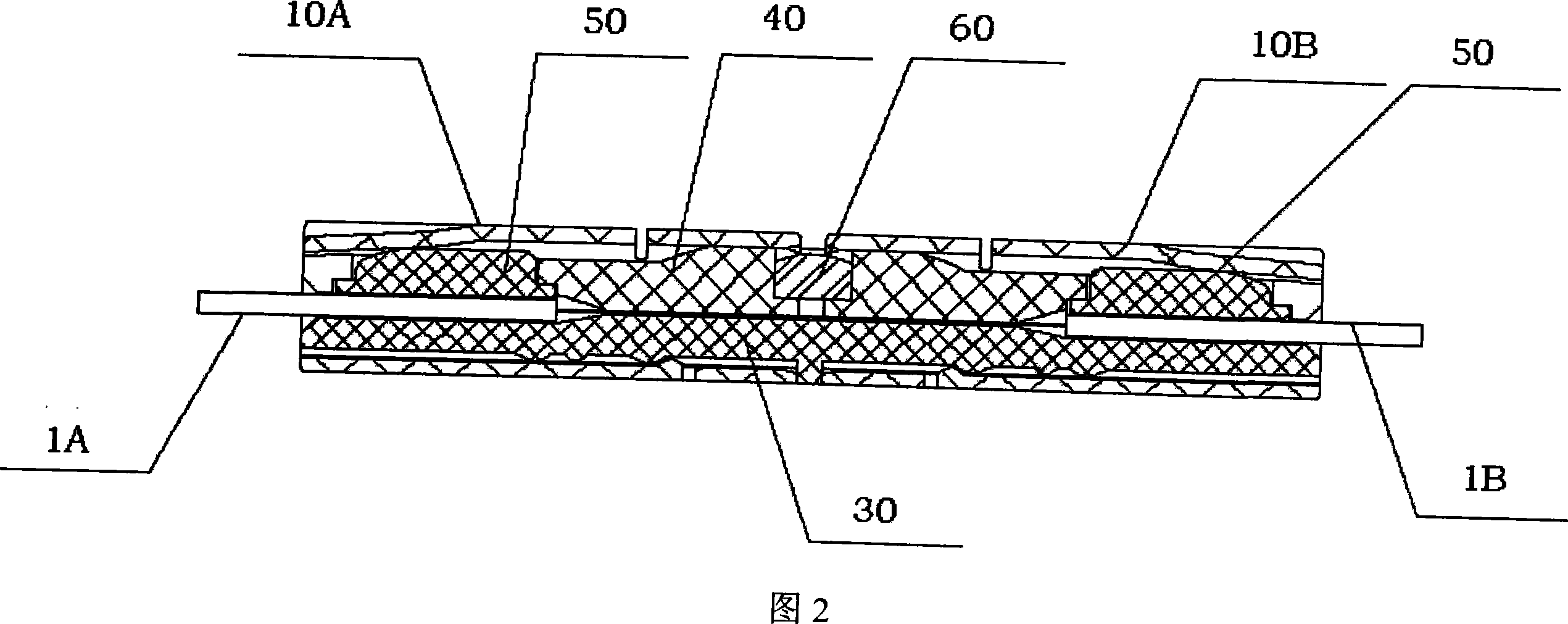
[0050] The joining member 20 is composed of a base part 30 , a pressure plate part 40 , and two cushion layer holding parts 50 . The buffer layer holding part 50 is embedded in the cavit...


PUM


Abstract

The invention provides an optical fiber connecting device which can connect every optical fiber with buffer covering layer but not need any other precise special optical fiber jointing device to improve the processing efficient. The optical fiber connecting device includes the jointing part and the shell. By the moving of shell in jointing part, the naked optical fiber can keep the connecting in jointing apparatus. At the same time, by the moving, the buffer layer holding part can press the optical buffer layer tightly to make optical fiber between the jointing parts and endure some axial and side outside force but has no influence to the optical connecting character.

Description

technical field [0001] The invention relates to a device for connecting optical fibers by means of a mechanical pressure fixing system. Belongs to fiber optic connection parts. Background technique [0002] With the development of optical fiber communication technology, more and more optical fibers are used, especially the development of fiber-to-the-home technology. It is urgent to solve the problem of fast and convenient optical fiber connection. Traditional optical fiber fusion splicing technology requires sophisticated and expensive equipment to terminate the optical fiber. For single-user or few-user construction, there will be many adverse effects on manpower and cost. Although the traditional optical fiber active connector is a mature product and can realize fast connection, due to the special requirements of the user on the length and size of the optical fiber, the port structure, etc., it cannot achieve one-to-one correspondence, and there are many unfavorable fac...

Claims


Application Information

Patent Timeline
IPC IPC(8): G02B6/38G02B6/36
Inventor 鲁仲明
Owner NANJING HUAMAI TECH
Why Eureka
Try Eureka