Luminous element

A technology of light-emitting elements and light-emitting diodes, which is applied in the direction of electrical elements, semiconductor devices, circuits, etc., and can solve the problems of low light output efficiency of light-emitting elements 10, etc.

Inactive Publication Date: 2008-02-27
IND TECH RES INST
View PDF0 Cites 3 Cited by
  • Summary
  • Abstract
  • Description
  • Claims
  • Application Information

AI Technical Summary

Problems solved by technology

In short, most of the excitation light 22 is seriously lost due to reflection or absorption inside the lig

Method used


Image

  • Luminous element
  • Luminous element
  • Luminous element

Examples


Embodiment Construction

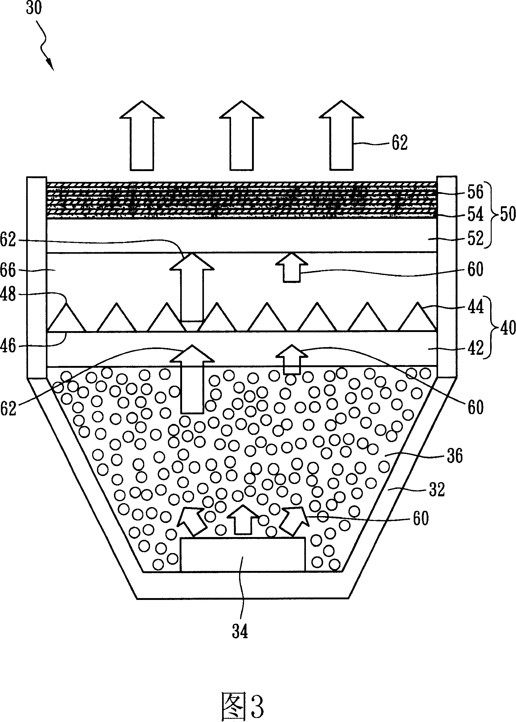
[0014] FIG. 3 illustrates a high light output efficiency light emitting element 30 of the present invention. The high light output efficiency light-emitting element 30 includes a substrate 32, at least one light-emitting diode chip 34 disposed on the substrate 32 and capable of generating an ultraviolet light 60, and a fluorescent substance disposed on the light-emitting diode chip 34 36 . A photonic crystal 40 disposed above the fluorescent substance 36 and an omnidirectional reflector 50 disposed above the photonic crystal 40 and capable of reflecting the ultraviolet light 60 to the fluorescent substance 36 . There is an air gap 66 between the photonic crystal 40 and the omnidirectional reflector 50 , and its refractive index is 1. Preferably, the fluorescent substance 36 covers the LED chip 34 .

[0015] The ultraviolet light 60 generated by the light-emitting diode chip 34 can excite the fluorescent substance (such as yttrium aluminum garnet) 36 to generate excitation lig...


PUM


Abstract

A kind of high-output-efficiency light emitting component includes a first substrate, a LED chip set on the first substrate, fluorescent material set on the said LED chip, a photonic crystal set above the said fluorescent material and a reflector which is set above the said photonic crystal and can reflect lights to the said fluorescent material. The said first substrate can be a metal cup; the said LED chip is set at bottom of the metal cup; the said photonic crystal includes a second substrate and even numbers of protrusions set on the second substrate; the said protrusion includes a bottom set on the second substrate and a tip of which the size is smaller than it of the said bottom; the said even numbers of protrusions can be triangle cylinder, half-circular cylinder, string-wave cylinder, pyramid or cone.

Description

technical field [0001] The invention relates to a light-emitting element, in particular to a light-emitting element with a concave-convex structure photonic crystal and a reflection plate. Background technique [0002] FIG. 1 illustrates a conventional light emitting device 10 . The light-emitting element 10 includes a substrate 12, a light-emitting diode chip 14 disposed on the substrate 12, a fluorescent substance (refractive index of about 1.5-1.6) 16 disposed on the light-emitting diode chip 14, and A transparent cover (refractive index about 1.5) 18 . The light 20 (such as ultraviolet light) can excite the fluorescent substance (such as red, green and blue fluorescent substance) 16 to generate red, green and blue excitation light 22 , and the red, green and blue excitation light 22 is mixed to form white light 24 . The light 20 generated by the LED chip 14 must pass through the fluorescent substance 16 and the transparent cover 18 , and then propagate to the outside o...

Claims


Application Information

Patent Timeline
IPC IPC(8): H01L33/00H01L33/48H01L33/58H01L33/60
Inventor 黄承扬朱正炜赵主立祁锦云
Owner IND TECH RES INST
Why Eureka
Try Eureka