Vacuum cleaning tool and method for its operation

A technology of cleaning machines and cleaners, which is applied to cleaning equipment, mechanical devices for controlling suction, suction nozzles, etc., and can solve problems such as lack of matching, insufficient matching, and insufficient cleaning results

Inactive Publication Date: 2008-03-05
DUPRO AG
View PDF1 Cites 12 Cited by
  • Summary
  • Abstract
  • Description
  • Claims
  • Application Information

AI Technical Summary

Problems solved by technology

Often the turbine power and the different floor conditions are not matched, or not matched well enough, which can lead to less than good cleaning results

Method used


Image

  • Vacuum cleaning tool and method for its operation
  • Vacuum cleaning tool and method for its operation
  • Vacuum cleaning tool and method for its operation

Examples


Embodiment Construction

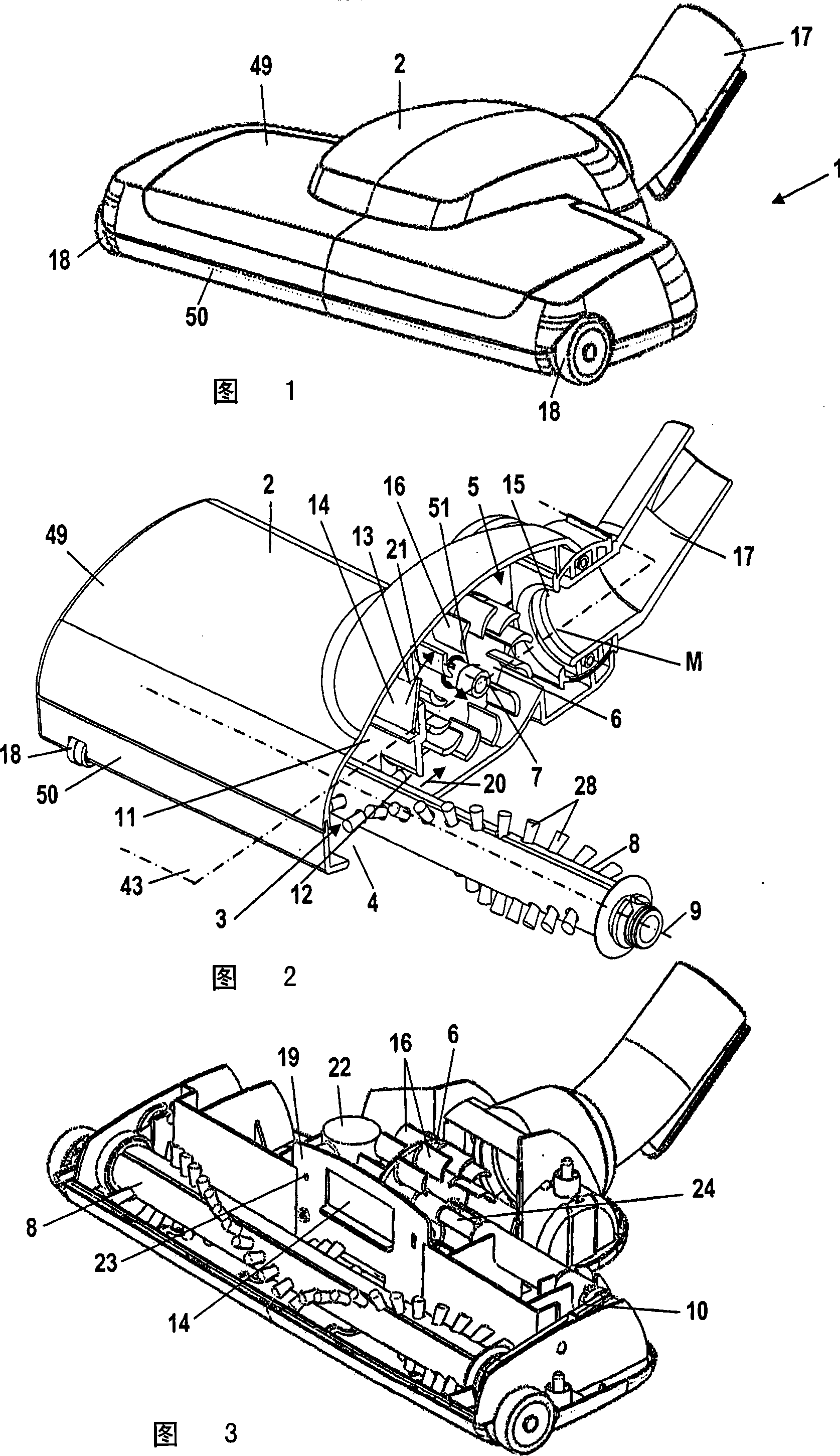
[0031] The extractor cleaner 1 shown in FIG. 1 has a housing 2 . The housing is composed of an upper case 49 and a lower case 50 . Two front wheels 18 are rotatably fastened to the housing. On the housing 2 of the vacuum cleaner 1 there is provided a connecting piece 17 for connection to the suction device of the vacuum cleaner.

[0032] FIG. 2 shows a sectional view of the suction cleaner. As shown in FIG. 2 , front wheels 18 may also be provided at the front side of the housing 2 . A suction hole 4 is formed in the lower case 50 . The suction opening extends over the entire width transversely to the working direction of the suction cleaning machine 1 . The suction hole 4 is a slit-shaped design. A cleaner, ie a brush roller 8 , is mounted rotatably about an axis of rotation 9 above the suction opening 4 . On this brush roller 8, many bristles 28 are fixed. Transversely to the working direction and parallel to the axis of rotation 9 of the brushroll 8, the housing 2 is...


PUM


Abstract

The suction cleaner has a housing (2) with a connecting piece (17) for connection to a suction device of the suction cleaning device. The suction cleaner has a suction hole (4) through which the working airflow flows into the housing (2); and a discharge hole (15) through which the working airflow leaves the housing (2) . The suction cleaner has a cleaner which is rotatably supported in the casing (2) and has a drive device for driving the cleaner to rotate. Good cleaning results and up to turbine power Good fit to different floor conditions. The method for operating the suction cleaner provides that the drive power of the cleaner is controlled as a function of the pressure (p) in the suction cleaner.

Description

technical field [0001] The invention relates to a suction cleaner having a housing with a connecting piece for a flow connection to a suction device of a suction cleaning device; A hole through which the working air flows into the housing; a discharge hole through which the working air leaves the housing; a cleaner which is rotatably supported in the housing; An air turbine for driving the cleaner in rotation, wherein the air turbine is rotatably mounted in a turbine chamber. [0002] The invention also relates to a method for operating an extraction cleaning machine. Wherein, the suction cleaning machine has a housing with a connection nipple for flow connection with a suction device of a suction cleaning device; a suction hole through which the working air flow flows into the housing body; a discharge hole through which the working air flow leaves the housing; a cleaner, which is rotatably supported in the housing; and also has a driving device for driving the cleaner to r...

Claims


Application Information

Patent Timeline
Patent Type & Authority Applications(China)
IPC IPC(8): A47L5/22A47L9/02
CPCA47L9/04A47L9/0072
Inventor P·沃瓦格
Owner DUPRO AG
Why Eureka
Try Eureka