Electrical device cooling structure in vehicle

A technology for electrical equipment and vehicles, which is applied in cooling/ventilation/heating transformation, electrical components, vehicle energy storage, etc. It can solve problems such as assembly restrictions, inability to cool converters, and longer and larger power supply devices.

Inactive Publication Date: 2008-03-12
HONDA MOTOR CO LTD
View PDF2 Cites 45 Cited by
  • Summary
  • Abstract
  • Description
  • Claims
  • Application Information

AI Technical Summary

Problems solved by technology

[0006] In this case, while the cooling air is cooling the battery, DC / DC converter, and inverter for driving the motor, the temperature gradually rises due to heat exchange , so even if the battery on the upstream side can be sufficiently cooled, there is still a possibility that the inverter for driving the motor on the downstream side cannot be sufficiently cooled
Furthermore, since the battery, DC / DC converter, motor drive inverter, and cooling fan are arranged in series, the size of the power supply unit becomes longer and larger. Causes the problem of requiring a large, high-performance cooling fan due to the increased flow resistance of the cooling air passage

Method used


Image

  • Electrical device cooling structure in vehicle
  • Electrical device cooling structure in vehicle
  • Electrical device cooling structure in vehicle

Examples


Embodiment Construction

[0034] Hereinafter, an embodiment of the present invention will be described with reference to FIGS. 1 to 9 .

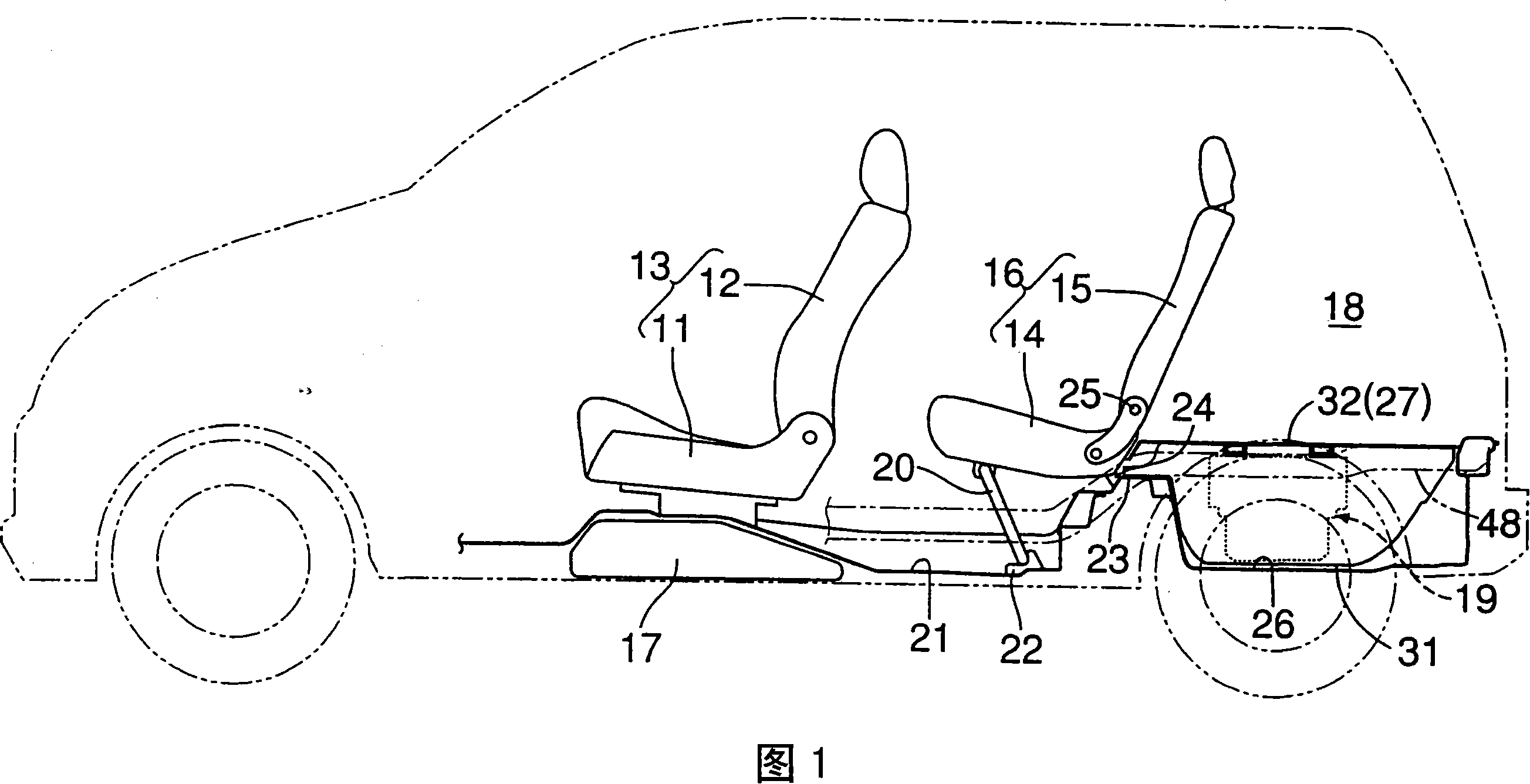
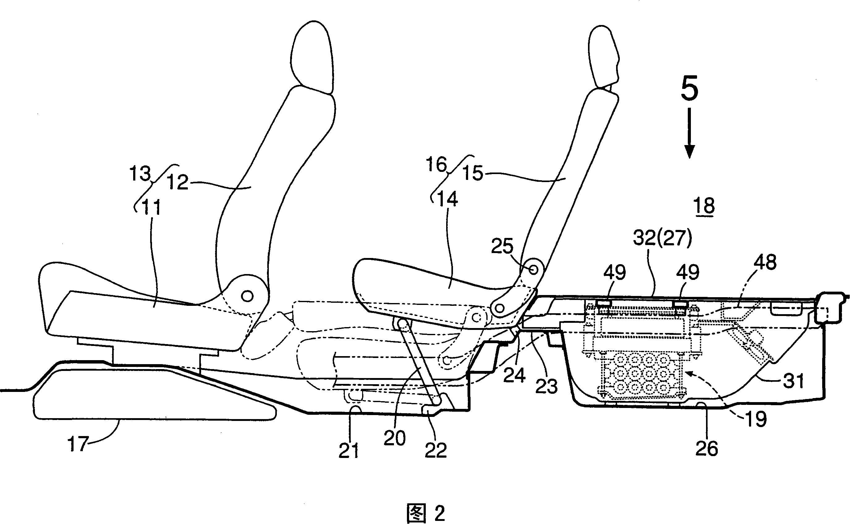
[0035] As shown in FIGS. 1 and 2 , a hybrid vehicle using an unillustrated engine and an electric motor as a driving source includes: a front seat 13 consisting of a seat cushion 11 and a seat back 12; a seat cushion 14 and a seat back 15; The rear seat 16. A fuel tank 17 is provided under a seat cushion 11 of the front seat 13 , and a power supply unit 19 for driving a motor is mounted under a luggage space 18 behind the rear seat 16 .

[0036] A pair of foldable pillars 20, 20 are arranged on the left and right below the seat cushion 14 of the rear seat 16. In the use state of the rear seat 16, the lower ends of the pillars 20, 20 are locked with the hooks 22, 22 arranged on the seat lower floor 21. and the rear end of the seat cushion 14 is locked and fixed with the seat cushion locking part 24 provided on the raised part 23 provided at the rear of the seat lower...


PUM


Abstract

In a power supply unit (19) disposed below a floor behind a seat, battery modules (37) are disposed in a lower position, and a DC / DC converter (41) and a motor driving inverter (42) are disposed side by side in a vehicle width direction above the battery modules (37). Thus, cooling air flowing from the front side to the rear side of a vehicle body is divided into upper and lower portions to cool in parallel the DC / DC (41) and the motor driving inverter (42) on the upper side and the battery modules (37) on the lower side. Thus, it is possible to simplify a passage of the cooling air to reducethe size of the entire power supply unit (19), and improve mountability of the power supply unit (19) on the vehicle body. Also, it is possible to apply cooling air at low temperature before heat exchange to all the battery module (37), the DC / DC converter (41), and the motor driving inverter (42), thereby enhancing cooling effect.

Description

technical field [0001] The present invention relates to a vehicle electrical equipment cooling structure, which installs electrical equipment including a battery for driving a motor for driving, a DC / DC converter, and an inverter for driving the motor under the floor behind the seats, and uses cooling air Cool the electrical equipment. Background technique [0002] It is known that Japanese Patent Application Laid-Open No. 2003-45392 discloses a technique in which a power supply device including a battery for driving a motor for driving a motor vehicle is mounted in a trunk behind a rear seat. , the battery is cooled by the cooling air supplied by the forced blower integrated with the power supply unit. [0003] In addition, Japanese Patent Laid-Open No. 2005-153827 also discloses a technology in which a battery including a battery for driving a motor for driving a vehicle, a DC / DC converter, an inverter for driving a motor, a cooling fan, etc. The power storage device is ...

Claims


Application Information

Patent Timeline
Patent Type & Authority Applications(China)
IPC IPC(8): B60K11/00B60K1/04B60K11/06B60L15/00H01M10/60H01M10/613H01M10/625H01M10/643H01M10/6563H01M10/6566H01M10/663
CPCB60L11/1877Y02T10/7241B60L2240/525Y02T10/7216Y02T10/7005B60L11/1874B60L2210/40B60L2210/10Y02E60/12Y02T10/705H05K7/20909Y02T10/645B60L2240/545B60L50/66B60L58/26Y02T10/70Y02T10/72
Inventor 深津友博西堀毅雄涩谷健太郎川田政夫山口浩央藤泽纯也中野笃小坂裕
Owner HONDA MOTOR CO LTD
Why Eureka
Try Eureka