Resilient disc sheet type solid compact spinning apparatus

A disc type and elastic disc technology, applied in spinning machines, textiles, papermaking, drafting equipment, etc., can solve the problems of out-of-sync speed of compact spinning device, inability to eliminate yarn quality, high production cost, etc., to achieve The effects of shortening the twisting distance, avoiding yarn breakage and improving work efficiency

Inactive Publication Date: 2008-03-12
朱爱萍
View PDF2 Cites 3 Cited by
  • Summary
  • Abstract
  • Description
  • Claims
  • Application Information

AI Technical Summary

Problems solved by technology

For example, a compact spinning device with patent No. 03228410.1 is provided with an air suction pipe with two ends fixed on two adjacent roller seats with air suction port and exhaust port, which is set outside the air suction pipe and corresponds to the position of the air suction port. The cohesive sleeve with a condensation groove in the circumferential direction of the cohesive sleeve, the tension device stuck in the cohesive sleeve, the air-permeable conveying ring and the transmission pressure device set on the cohesive sleeve, the compact spinning device can make the fiber bundle output by the front roller Under the action of negative pressure generated by the exhaust system, it is adsorbed on the air-permeable conveying ring, and under the action of the pressurized transmission device and the air-permeable conveying ring, the fiber bundle is tightened and straightened to achieve twisting into yarn. The yarn device can better solve the original "hairiness" problem and improve the yarn quality, but there are also some shortcomings, such as complex structure and high production cost; and the compact spinning device and the roller are driven by different power devices. It is easy to cause the speed of the compact spinning device to be out of sync with the speed of the rollers, resulting in yarn blocking and yarn breakage
The twisting triangle cannot be eliminated and the yarn quality will be affected

Method used


Image

  • Resilient disc sheet type solid compact spinning apparatus
  • Resilient disc sheet type solid compact spinning apparatus
  • Resilient disc sheet type solid compact spinning apparatus

Examples


Embodiment Construction

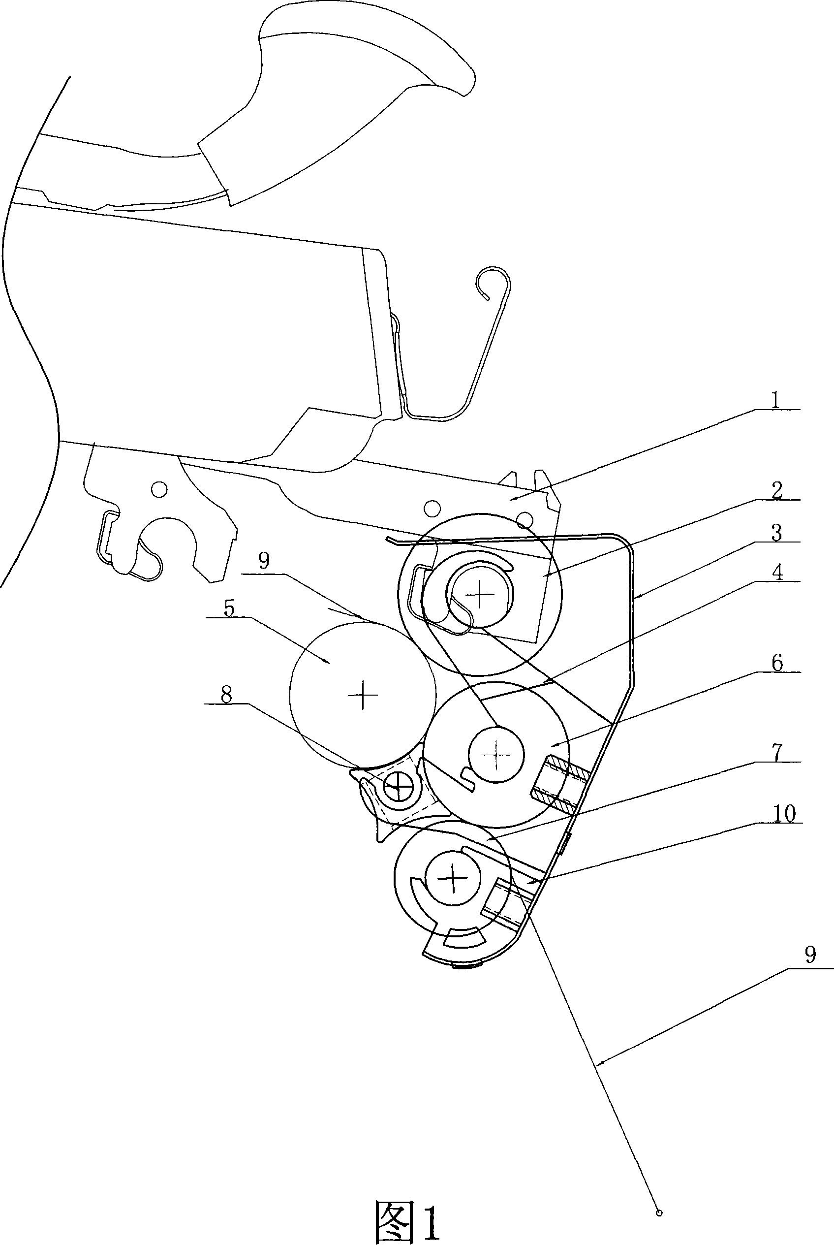
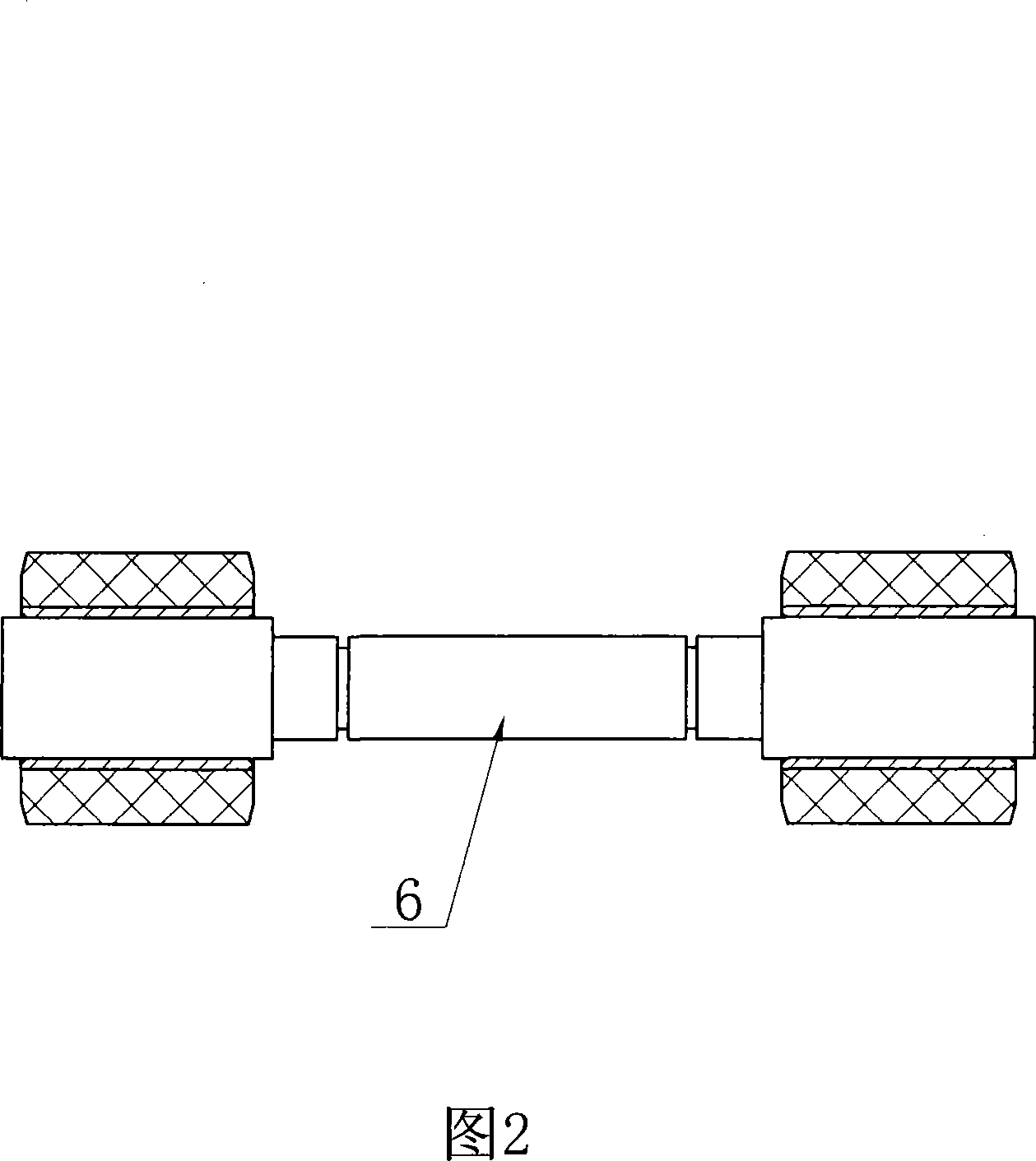
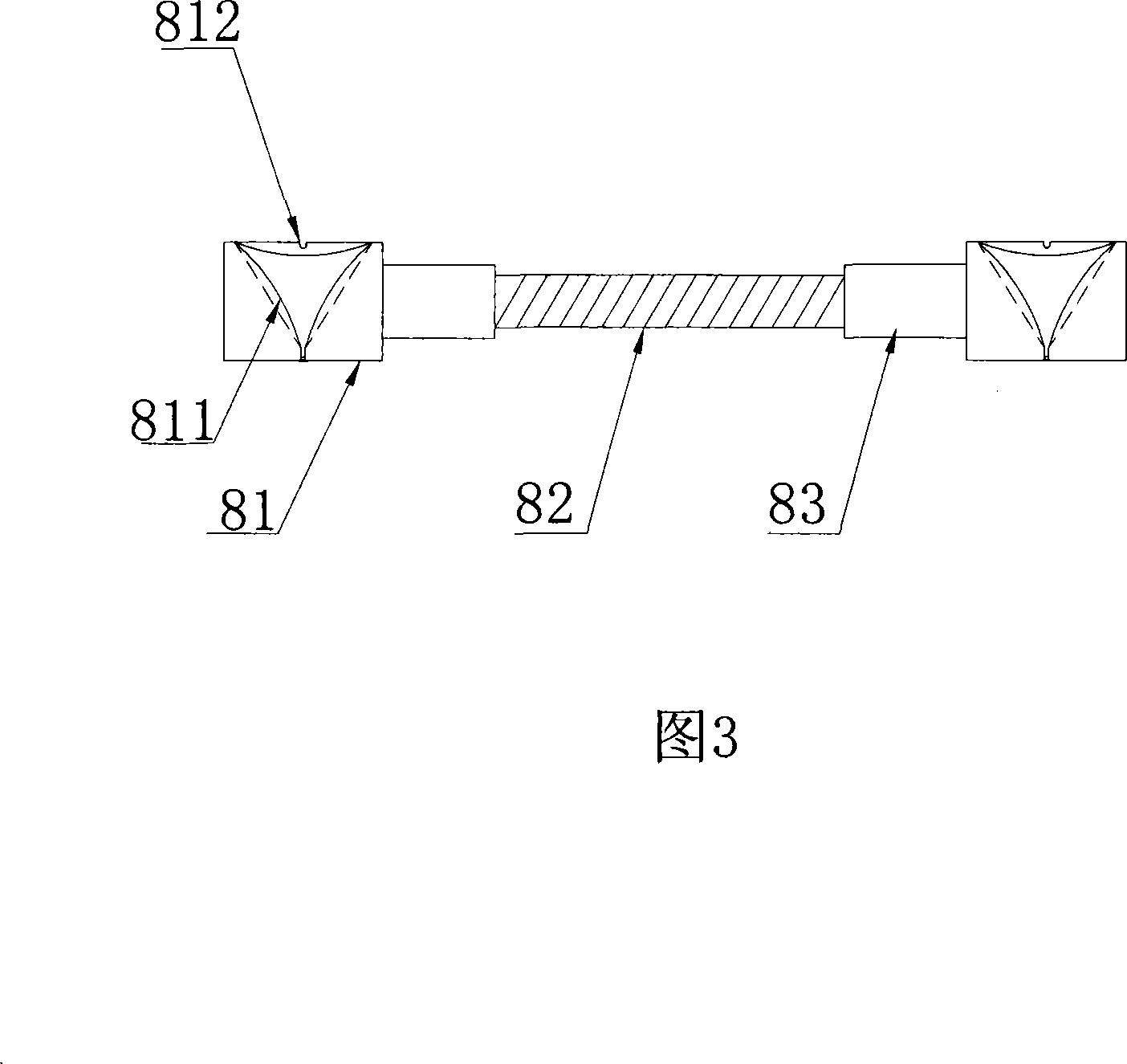
[0017] As shown in Fig. 1, Fig. 2 and Fig. 4, the lower top roller 2 is installed on the cradle 1 of the spinning frame, the bottom roller 5 is installed on the fuselage below the cradle 1, and the lower top roller 2 is pressed tightly On the roller 5, one end of the upper fixing seat 4 is connected to the shaft of the lower top roller 2, and the other end is installed on the spring plate 3, as shown in Figure 5 and Figure 6, the spring plate 3 is a bow-shaped plate with two ends bent, and the spring The upper end of the plate 3 is fixedly connected to the cradle 1, and a lower fixing seat 10 is installed on the lower end bending part of the spring plate 3, and a middle top roller 6 and an elastic disk 8 are installed on the upper fixing seat 4, and the middle top roller 6 is tightly fastened. Press on the bottom roller 5, and an elastic disk 8 is arranged between the middle top roller 6 and the bottom roller 5. One side of the elastic disk 8 is pressed on the bottom roller 5, ...


PUM


Abstract

The invention discloses an elastic disc type three-dimensional compact spinning device that belongs to the technical field of textile machines. The device comprises a rocking shelf mounted on the spinning machine; the rocking shelf is arranged with a lower leather-covered roll; the lower roller is positioned below the rocking shelf; the rocking shelf is fixed with a spring plate; the spring plate is arranged with a central leather-covered roll and a supper-low leather-covered roll; the central leather-covered roll is mounted below the lower leather-covered roll, and tightly pressed on the lower roller; the super-low leather-covered roll is tightly pressed on the central leather-covered roll; between the central leather-covered roll and the lower roller, an elastic disc is provided; the elastic disc comprises a bundling disc and an elastic bar; one side of the bundling disc is pressed on the lower roller through the elastic bar; the other side tightly leans against the central leather-covered roll; on one side where the bundling disc tightly leans against the central leather-covered roll, an arc-shaped slot is opened with a horn-shaped breach in width that gradually becomes smaller. The invention is characterized by perfect bundling effects and convenient installation and utilization.

Description

technical field [0001] The invention relates to a textile machine, in particular to an elastic disc type three-dimensional compact spinning device applied to a spinning frame. Background technique [0002] In the spinning process of the traditional spinning frame, after the drafted sliver leaves the front roller with a certain width and in a free state, it is immediately processed into a yarn, and a spun yarn is formed in the yarn forming area In the triangular area, because the loose fibers in the spinning triangular area cannot be well controlled, many fiber whiskers around the yarn sliver will be scattered in advance and cannot be bundled, and the scattered fibers will protrude out of the yarn because they cannot be squeezed into the yarn The "hairiness" that occurs in spinning is formed, which seriously affects the yarn quality and reduces the fiber utilization. Therefore, it is necessary to improve the conveying form of the sliver before twisting, even if the sliver is...

Claims


Application Information

Patent Timeline
Patent Type & Authority Applications(China)
IPC IPC(8): D01H5/72
Inventor 刘光容
Owner 朱爱萍
Why Eureka
Try Eureka