Ethernet service assembly device and method

An Ethernet and business technology, applied in the field of communication transmission, can solve the problems of unfavorable promotion and application, complex structure level, multiple processing levels, etc., and achieve the effect of reducing technical complexity, simple structure and processing level, and strong reliability

Inactive Publication Date: 2008-03-12
GLOBAL INNOVATION AGGREGATORS LLC
View PDF0 Cites 13 Cited by
  • Summary
  • Abstract
  • Description
  • Claims
  • Application Information

AI Technical Summary

Problems solved by technology

[0003] The defects in the existing technology are: multi-layer processing is required for Ethernet service aggregation, such as GFP / HDLC encapsulation, virtual container mapping and processing, SDH framing processing, etc., the structure of the device is complex, and the processing layer More, the cost is relatively high, which is not conducive to large-scale promotion and application, so it is necessary to improve

Method used


Image

  • Ethernet service assembly device and method
  • Ethernet service assembly device and method
  • Ethernet service assembly device and method

Examples


Embodiment 1

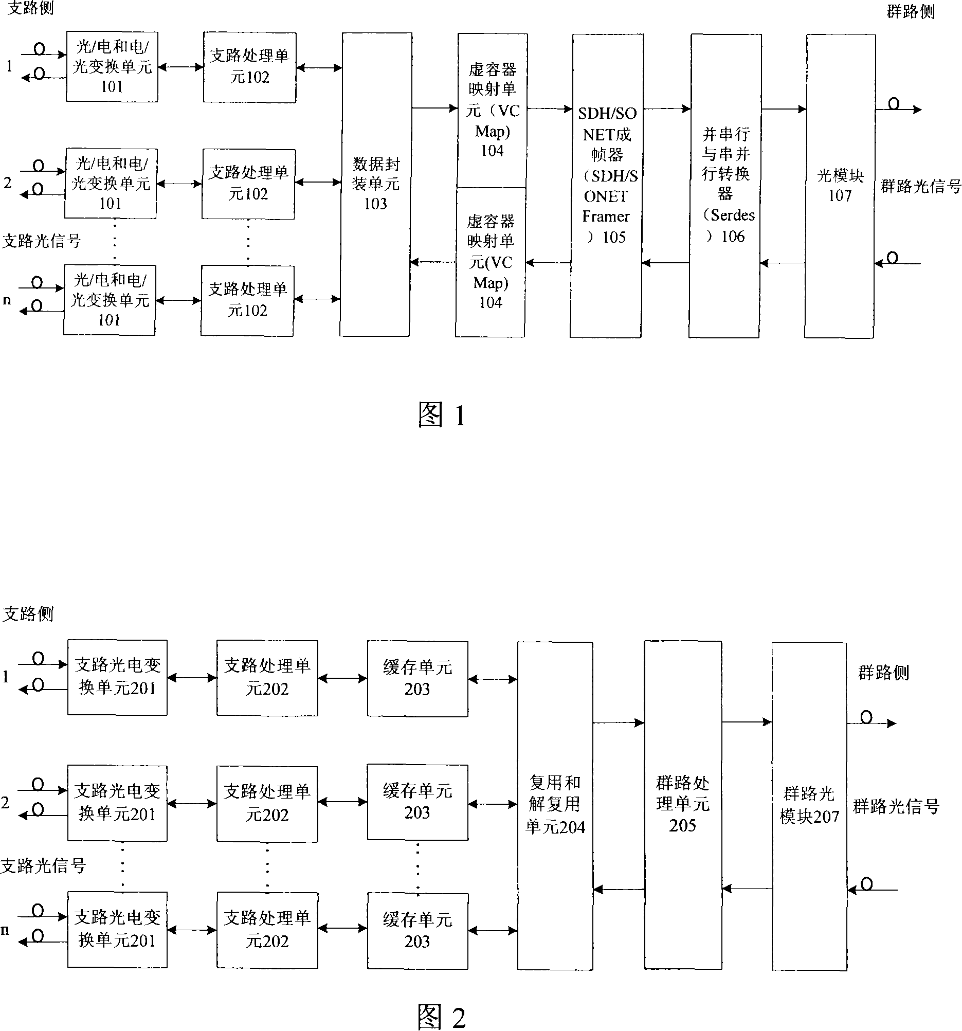
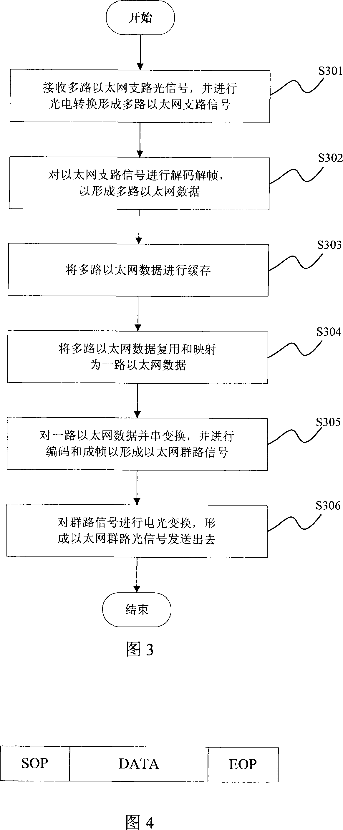
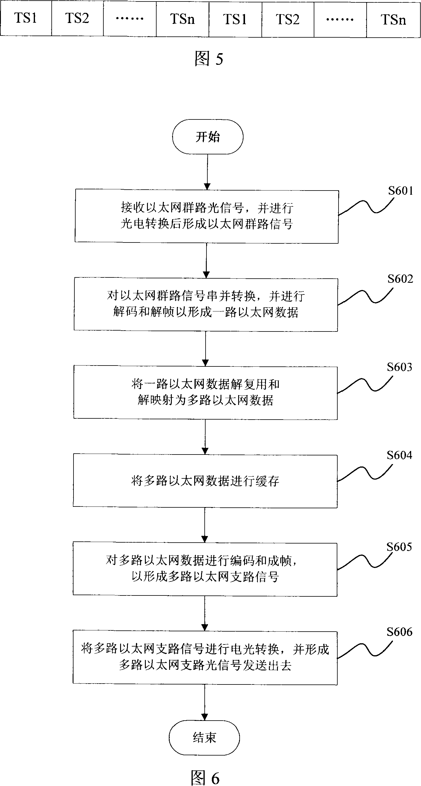
[0081] The converging process of Embodiment 1 is as follows: the branch side signals GE1 and GE2 enter the corresponding branch photoelectric conversion unit 701, and the branch photoelectric conversion unit 701 performs photoelectric conversion on the GE1 and GE2 signals to turn them into electrical signals and send them to PCS and MAC processing unit 702 . PCS and MAC processing unit 702 performs PCS and MAC processing on the Ethernet electrical signal, completes Ethernet frame positioning and 8B / 10B decoding, and parses the Ethernet frame, performs CRC checksum monitoring on the Ethernet frame, and then The GE1 and GE2 signals are divided into several data segments, and each data segment is added with a packet header SOP and a packet tail EOP, and is written into the corresponding FIFO buffer unit 703 according to the data message format in FIG. 4 . The time division multiplexing and demultiplexing unit 705 polls the data of each tributary FIFO buffer unit 703 by time slice...

Embodiment 2

[0084]The converging process of Embodiment 2 is as follows: the branch side signals GE and FE enter the corresponding branch photoelectric conversion unit 701, and the branch photoelectric conversion unit 701 performs photoelectric conversion on the GE and FE signals to make them into electrical signals and send them to the PCS and a MAC processing unit 702 . The PCS and MAC processing unit 702 performs PCS and MAC processing on the Ethernet electrical signal, completes frame positioning of the Ethernet, 8B / 10B decoding of the GE signal, and 4B / 5B decoding of the FE signal, and parses the Ethernet frame. The network frame is checked and monitored by CRC, and then the GE and FE signals are divided into several data segments, and each data segment is added with the packet header SOP and the packet tail EOP, and is written into the PCS and PCS of the branch according to the format of the FIFO in Figure 4. The FIFO cache unit 703 corresponding to the MAC processing unit 702 . The...


PUM


Abstract

The utility model discloses a Ethernet service integration device, which comprises a couple of branch processing unit, a couple of the buffer units, a diplex and de-diplex unit and a cluster processing unit. The branch processing unit is used to code / decode and frame / de-frame the multi-Ethernet branches; the buffer unit is used to complete the buffer of multi-Ethernet data; the diplex and de-diplex unit is used to diplex / de-diplex and map / de-map the multi-Ethernet data; the cluster processing unit is used to conduct the parallel / series switch for the Ethernet data as well as coding / decoding and frame / de-frame. The utility model also provides the Ethernet service integration method, which includes the integration steps and / or de-integration steps. Based on the branch processing unit, the buffer units, the diplex and de-diplex unit and the cluster processing unit, the utility model realizes the integration and de-integration of the Ethernet service. The structure and process thereof is simple, so as to greatly simplify the technical complexity and the utility model has the advantages of low cost and high reliability, so as to be suitable for the popularization.

Description

technical field [0001] The invention relates to the field of communication transmission, in particular to an Ethernet service convergence device and method. Background technique [0002] At present, with the rapid increase of Ethernet services accessed by transmission equipment, the requirements for transmission equipment are getting higher and higher, especially the transmission equipment is required to have multiple customer service ports, efficient aggregation capabilities, and low cost advantages. An Ethernet service aggregation device provided in the prior art is shown in FIG. 1 , including: an optical / electrical and electrical / optical conversion unit 101, a branch processing unit 102, a data encapsulation unit 103, and a virtual container mapping (VCMap) unit 104 , SDH / SONET framer (Synchronous Digital Hierarchy / Synchronous Optical Network Framer, Synchronous Digital Hierarchy / Synchronous Optical Network Framer) 105, parallel serial and serial parallel converter (SERia...

Claims


Application Information

Patent Timeline
Patent Type & Authority Applications(China)
IPC IPC(8): H04L12/28H04L12/56H04J3/16
Inventor 夏亮
Owner GLOBAL INNOVATION AGGREGATORS LLC
Why Eureka
Try Eureka