
Method and device for performing demodulation to digital signal using synchronous clock signal

A technology for synchronizing clock signals and digital signals. It is used in synchronization/start-stop systems, automatic power control, instruments, etc. It can solve problems such as large synchronization clock jitter, poor clock accuracy, and synchronization loop loss, and achieve increased frequency locking. The effect of range, jitter reduction, and effective recovery

Inactive Publication Date: 2011-09-21
ZTE INTELLIGENT IOT TECH
View PDF0 Cites 0 Cited by
  • Summary
  • Abstract
  • Description
  • Claims
  • Application Information

AI Technical Summary

Problems solved by technology

[0004] The object of the present invention is to provide a method and device for demodulating digital signals using a synchronous clock signal in a digital communication system, which is used to solve the large synchronous clock jitter due to insufficient frequency coverage of the synchronous tracking loop in the prior art; Especially due to the poor clock accuracy of the sender, the communication time is very short, and the digital phase-locked loop needs a certain period of time to synchronize, which leads to the problem that the synchronization loop loses lock when valid data is sent, and the signal cannot be demodulated correctly. Improve the precision of the digital synchro tracking loop and increase the effect of the locking range of the digital synchro tracking loop

Method used


Image

  • Method and device for performing demodulation to digital signal using synchronous clock signal
  • Method and device for performing demodulation to digital signal using synchronous clock signal
  • Method and device for performing demodulation to digital signal using synchronous clock signal

Examples


Embodiment Construction

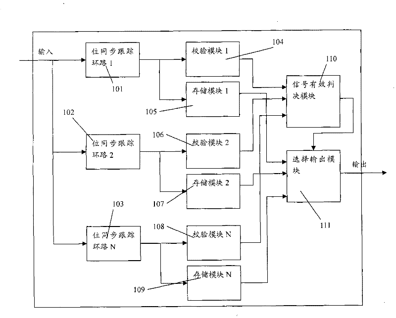
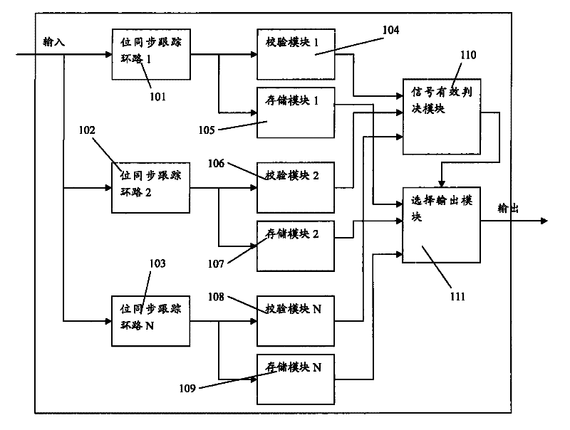
[0029] see figure 1 , which is a structural diagram of a preferred embodiment of a device for demodulating digital signals using a synchronous clock signal in a digital communication system according to the present invention. It can be applied to the bit synchronization recovery of the electronic tag to the reader signal in the RFID system, and can also be applied to other digital communication systems that need bit synchronization recovery.

[0030] As shown in the figure: the device consists of bit synchronous tracking loops 101, 102, 103, verification modules 104, 106, 108, signal valid judgment module 110, and storage modules 105, 107, 109 storing the current transmission of the synchronous tracking loop output The data and selection output module 111 is composed. The functions and connections of each module are:

[0031] N parallel bit synchronous tracking loops 101, 102, 103, they respectively work on overlapping locked frequency ranges to recover bit synchronously fro...


PUM


Abstract

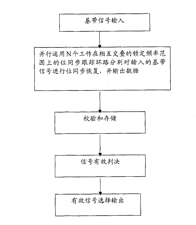
The present invention relates to a method for demodulating digital signals by using synchronous clock signals in a digital communication system. The method comprises the steps that first, the bit-synchronous restoration is performed for inputting signals by using two loops and more than two loops of bit-synchronous tracking loops which work within a mutually overlapping locking frequency range inparallel, and then data is output; second, all loops are decoded in parallel, and verification and storage are performed through the output data; third, after the data sent for once is accomplished, a loop of correct demodulated signals is selected and output according to the verification result. The device of the method comprises N loops of paralleled bit-synchronous tracking loops, N loops of verification modules, N loops of storage modules, a signal valid determination module and a selection output module. The present invention solves the problems that because the frequency coverage area of the synchronous tracking loops is insufficient in the prior art, the synchronous clock shakes severely, the synchronous loops are out of lock when the valid data is sent, and the signals cannot be demodulated correctly, thus achieving the effects that the precision of the digital synchronous tracking loops is improved, and the locking range of the digital synchronous tracking loops is increased.

Description

technical field [0001] The present invention relates to the technical field of bit synchronization of a digital communication system, in particular to a method and device for demodulating a digital signal using a synchronous clock signal in a digital communication system, which can be applied to an RFID (Radio Frequency Identification, radio frequency identification) system The bit synchronization recovery of the electronic tag to the reader signal can also be applied to other digital communication systems that require bit synchronization recovery. Background technique [0002] In a digital communication system, in order to realize signal demodulation, one way is to extract a synchronous clock signal from a digital signal, and then use the synchronous clock signal to demodulate the digital signal. [0003] Taking the application of RFID as an example, the problems existing in the signal from the electronic tag to the reader are: the sending signal is discontinuous, and the t...

Claims


Application Information

Patent Timeline
Patent Type & Authority Patents(China)
IPC IPC(8): H04L25/40H03L7/07G06K7/016
Inventor 曾祥希王学寰
Owner ZTE INTELLIGENT IOT TECH
Learn More