Control device for internal combustion engine
A technology for controlling equipment and internal combustion engines, applied in mechanical equipment, engine control, fuel injection control, etc., can solve problems such as inappropriate correction of fuel injection amount, and achieve the effect of proper fuel injection amount and proper correction
- Summary
- Abstract
- Description
- Claims
- Application Information
AI Technical Summary
Problems solved by technology
Method used
Image
Examples
no. 1 example
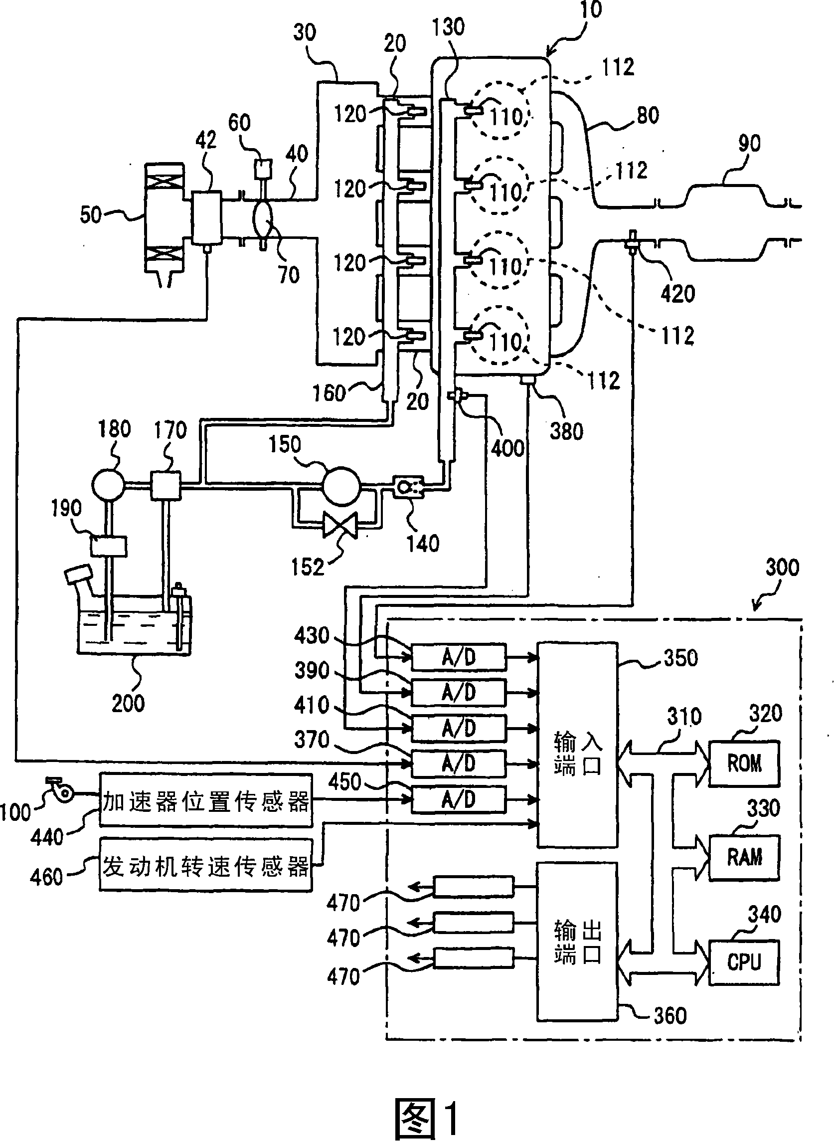
[0052] Fig. 1 schematically shows the configuration of an engine system controlled by an engine ECU (Electronic Control Unit), which is an internal combustion engine control device according to a first embodiment of the present invention. Although FIG. 1 shows an inline four-cylinder gasoline engine, the application of the present invention is not limited to the shown engine, and the present invention can be applied to various types of engines such as V-type six-cylinder engines, V-type eight-cylinder engines, and the like.
[0053] As shown in FIG. 1 , engine 10 includes four cylinders 112 connected to a common surge tank 30 via corresponding intake manifolds 20 . The surge tank 30 is connected to an air cleaner 50 via an intake pipe 40 . An airflow meter 42 and a throttle valve 70 driven by an electric motor 60 are provided in the intake pipe 40 . The opening position of the throttle valve 70 is controlled independently of the accelerator pedal 100 based on an output signal...
no. 2 example
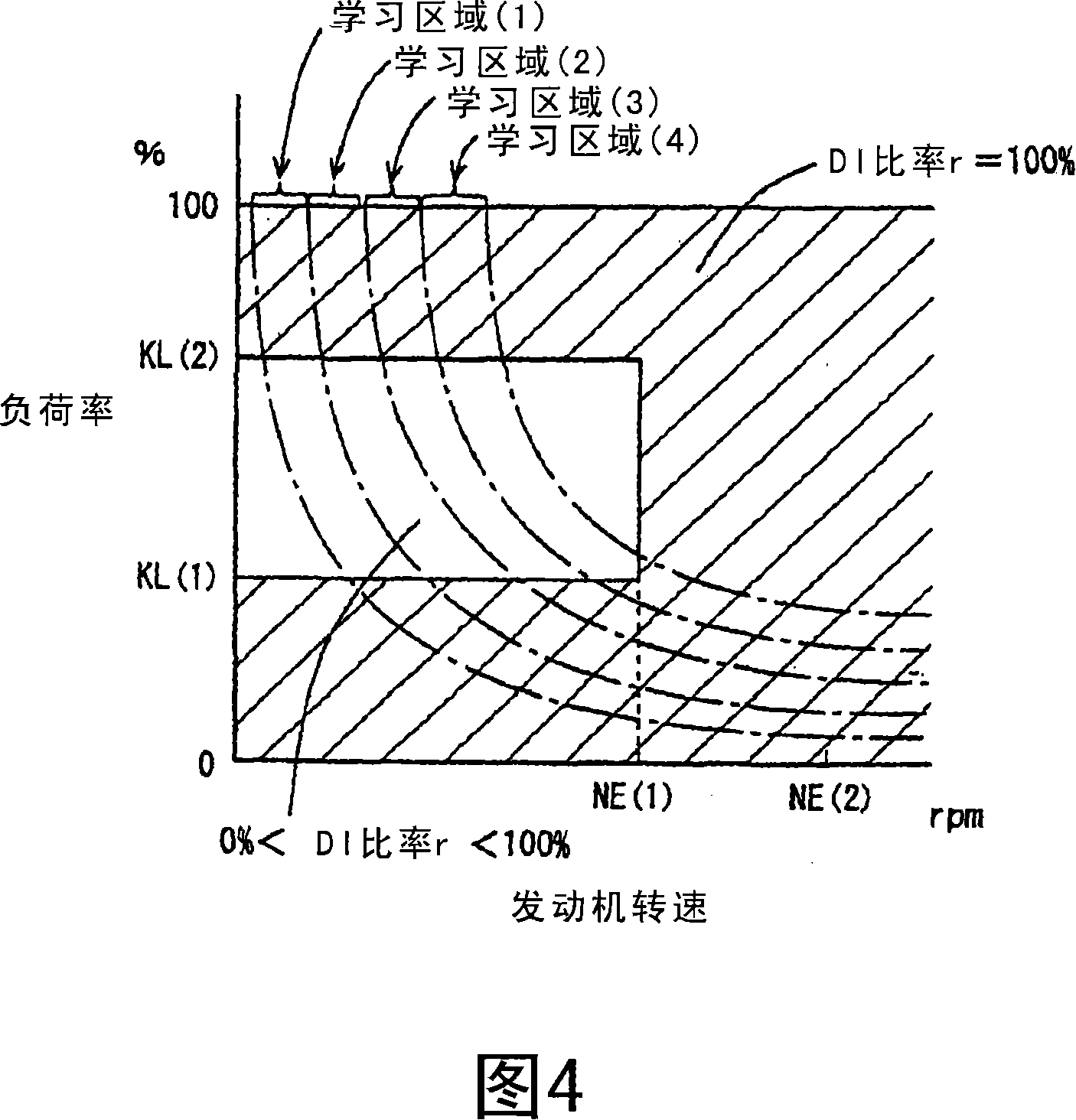
[0098] Referring to Figs. 10 to 12, a second embodiment of the present invention will be described. This embodiment differs from the previously described first embodiment in that the already calculated learning values are used to set learning values in other learning areas. Since this embodiment is otherwise the same as the previously described first embodiment and has the same functions, its detailed description will not be repeated.
[0099] A control structure of a program executed in engine ECU 300 serving as the control device for the internal combustion engine according to the present embodiment will be described with reference to FIG. 10 .
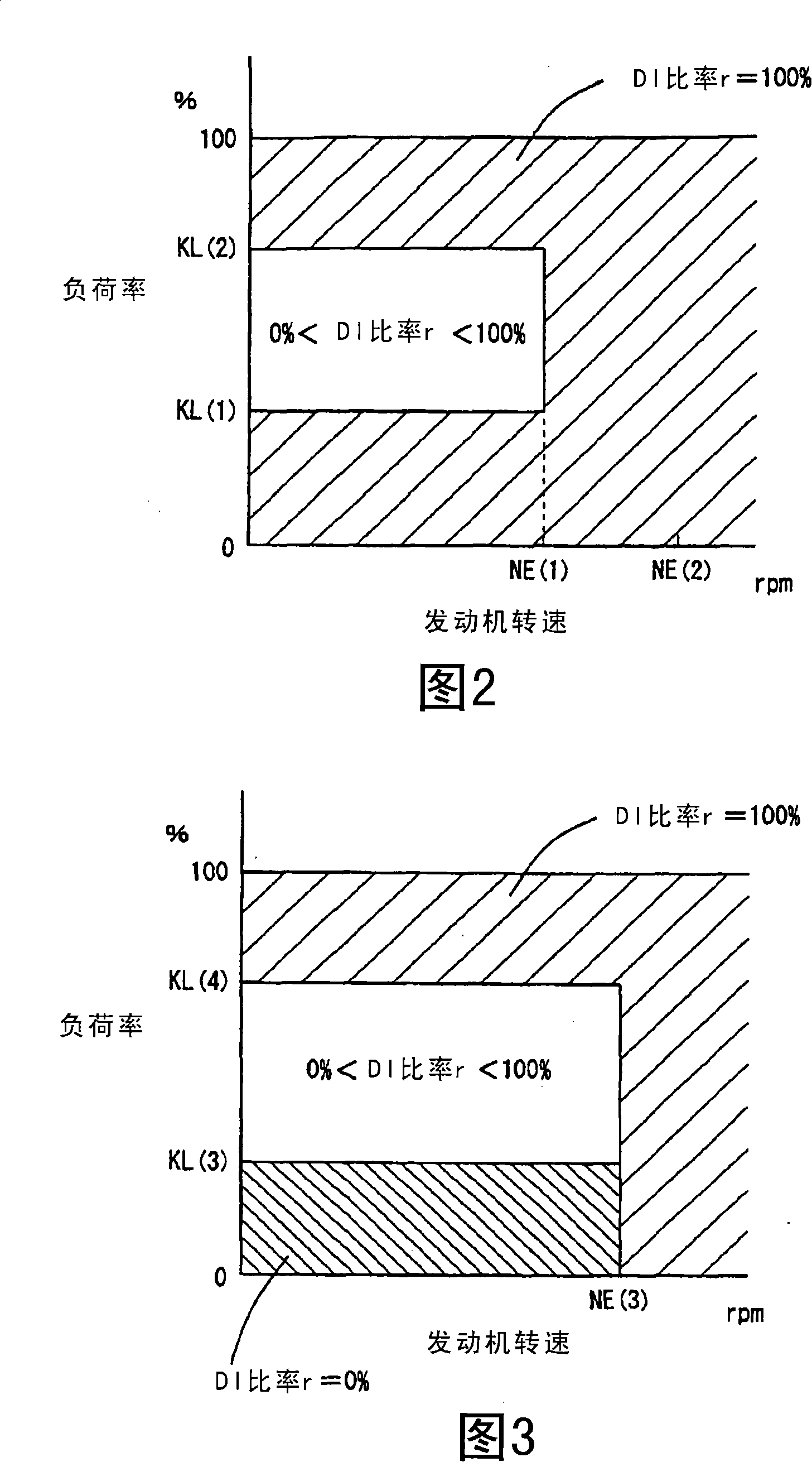
[0100] At step (hereinafter, step is abbreviated as S) 100, engine ECU 300 identifies an injection region based on a map showing DI ratio r in FIGS. 2 and 3 . At S202 , engine ECU 300 identifies a learning area based on the intake air amount detected by airflow meter 42 .
[0101] At S204 , engine ECU 300 detects the air-fuel ...
no. 3 example
[0118] Referring to Fig. 13 and Fig. 14, a third embodiment of the present invention will be described. In the present invention, the DI ratio r is calculated using a map different from that of the previously described first embodiment.
[0119] In other respects, since the configuration, processing flow, and functions thereof are the same as those in the foregoing first embodiment, detailed description thereof will not be repeated.
[0120] Referring to FIG. 13 and FIG. 14 , each map representing the fuel injection ratio between in-cylinder injector 110 and intake manifold injector 120 as information on the operating state of engine 10 will be described below. . These maps are stored in the ROM 320 of the engine ECU 300 . FIG. 13 is a map for a warm state of the engine 10 , and FIG. 14 is a map for a cold state of the engine 10 .
[0121] Fig. 13 and Fig. 14 are different from Fig. 2 and Fig. 3 in the following points. In the region where the engine speed of the engine 10...
PUM
 Abstract
Description
Claims
Application Information
 - R&D
- Intellectual Property
- Life Sciences
- Materials
- Tech Scout
- Unparalleled Data Quality
- Higher Quality Content
- 60% Fewer Hallucinations
Browse by: Latest US Patents, China's latest patents, Technical Efficacy Thesaurus, Application Domain, Technology Topic, Popular Technical Reports.
© 2025 PatSnap. All rights reserved.Legal|Privacy policy|Modern Slavery Act Transparency Statement|Sitemap|About US| Contact US: help@patsnap.com


