Superconductive cable

一种超导电缆、电缆的技术,应用在超导电缆,DC传输系统领域,能够解决电流大、温度过度上升、AC损耗大等问题

Inactive Publication Date: 2008-03-12
SUMITOMO ELECTRIC IND LTD
View PDF0 Cites 19 Cited by
  • Summary
  • Abstract
  • Description
  • Claims
  • Application Information

AI Technical Summary

Problems solved by technology

[0003] In the case of AC transmission by using the above-mentioned superconducting cable, not only the AC loss due to inductance is large but also the current at the time of short circuit is large, and the temperature may rise excessively due to the loss at that time

Method used


Image

  • Superconductive cable
  • Superconductive cable
  • Superconductive cable

Examples


example 1

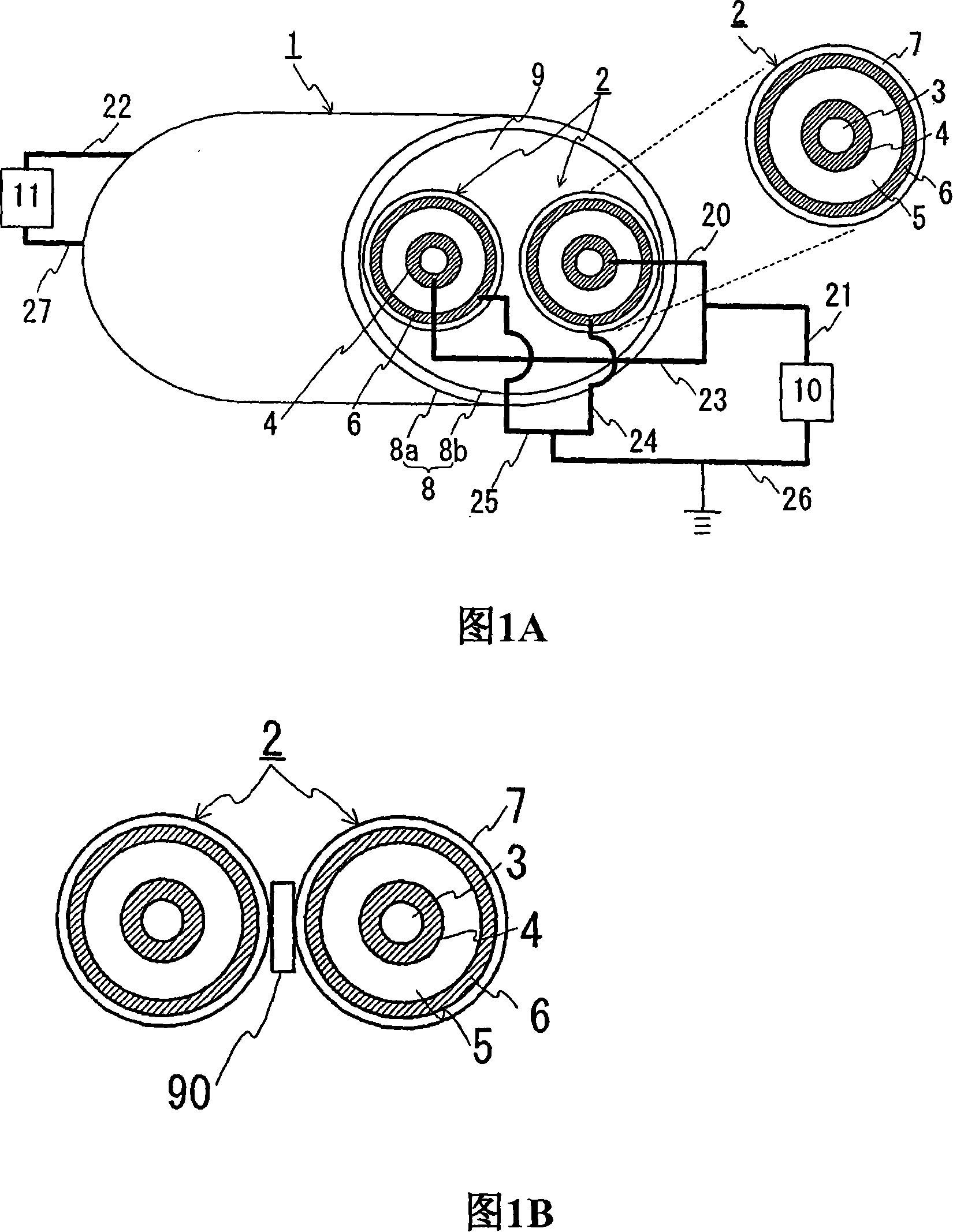
[0063]FIG. 1(A) is a schematic structural view showing a state in which a DC transmission line for unipolar transmission is constructed by using the superconducting cable of the present invention. FIG. 1(B) is a schematic cross-sectional view showing a state where spacers are provided between cable cores in a superconducting cable. In the following drawings, the same reference numerals denote the same elements. The superconducting cable 1 has a structure in which two cable cores 2 each having a superconducting conductor layer 4 and an outer layer made of a superconducting material are twisted together and housed in a heat insulating tube 8. superconducting layer6. Each cable core 2 has a shaper 3 , a superconducting conductor layer 4 , an insulating layer 5 , an outer superconducting layer 6 and a protective layer 7 in order from the center.

[0064] In this example, the superconducting conductor layer 4 and the outer superconducting layer 6 were formed by using a Bi-2223-ba...

example 2

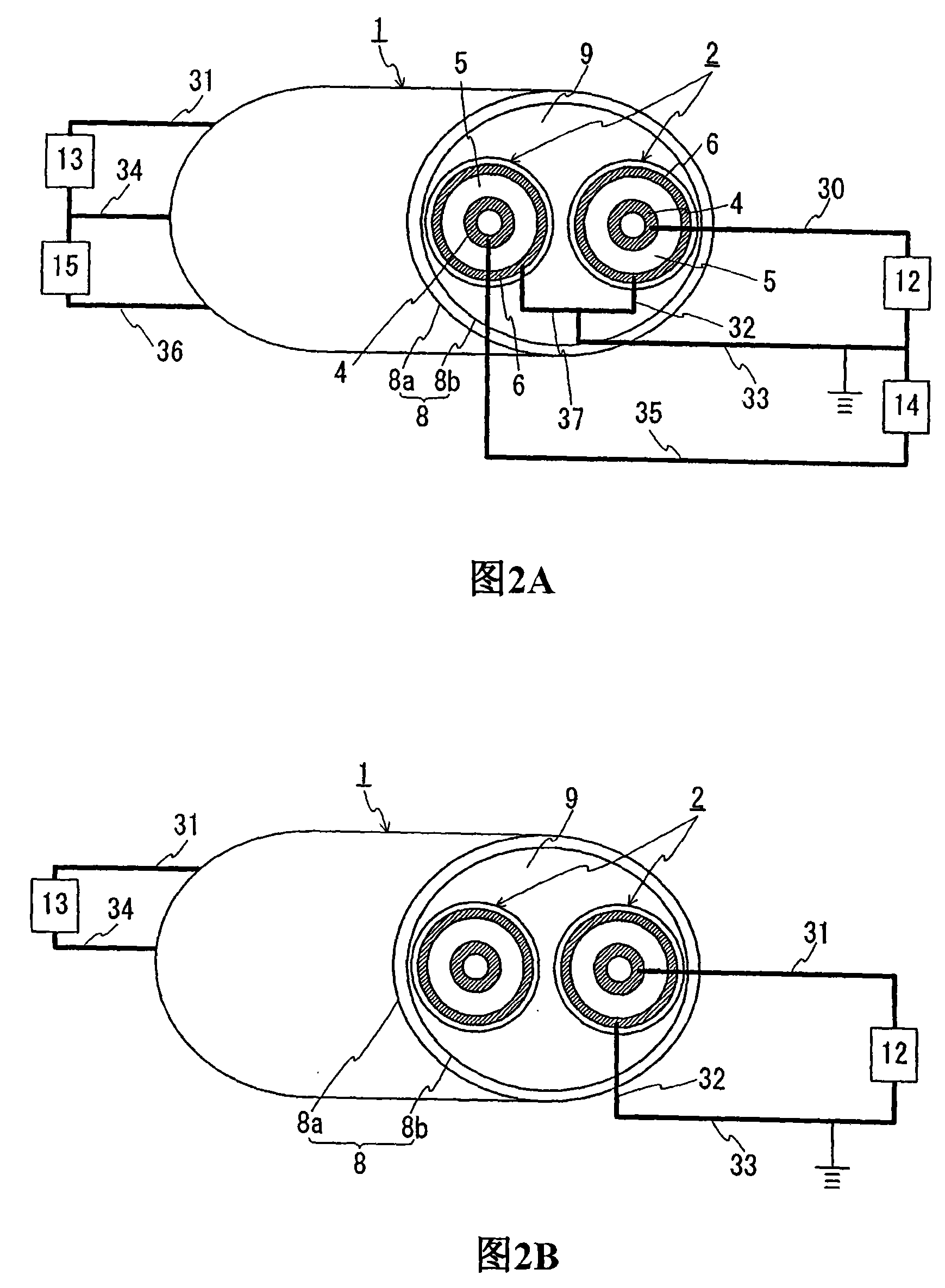
[0069] Next, the case where bipolar transmission is performed is explained. FIG. 2(A) is a schematic structural view showing the state of constructing a DC transmission line for bipolar transmission by using the superconducting cable of the present invention. (B) is a structural schematic diagram showing a state in which a DC transmission line for unipolar transmission is constructed by using a superconducting cable layer of one of the cores and an outer superconducting layer. The superconducting cable 1 used in Example 1 can also be used for bipolar transmission. For bipolar transmission, it is recommended to construct the transmission line as shown in Fig. 2(A). More specifically, one end of the superconducting conductor layer 4 provided in one of the cores 2 (the right core 2 in FIG. to the AC system (not shown). The other end of the same superconducting conductor layer 4 is connected via a lead wire 31 to a DC-AC converter 13, which is connected to an AC system (not sho...

example 3

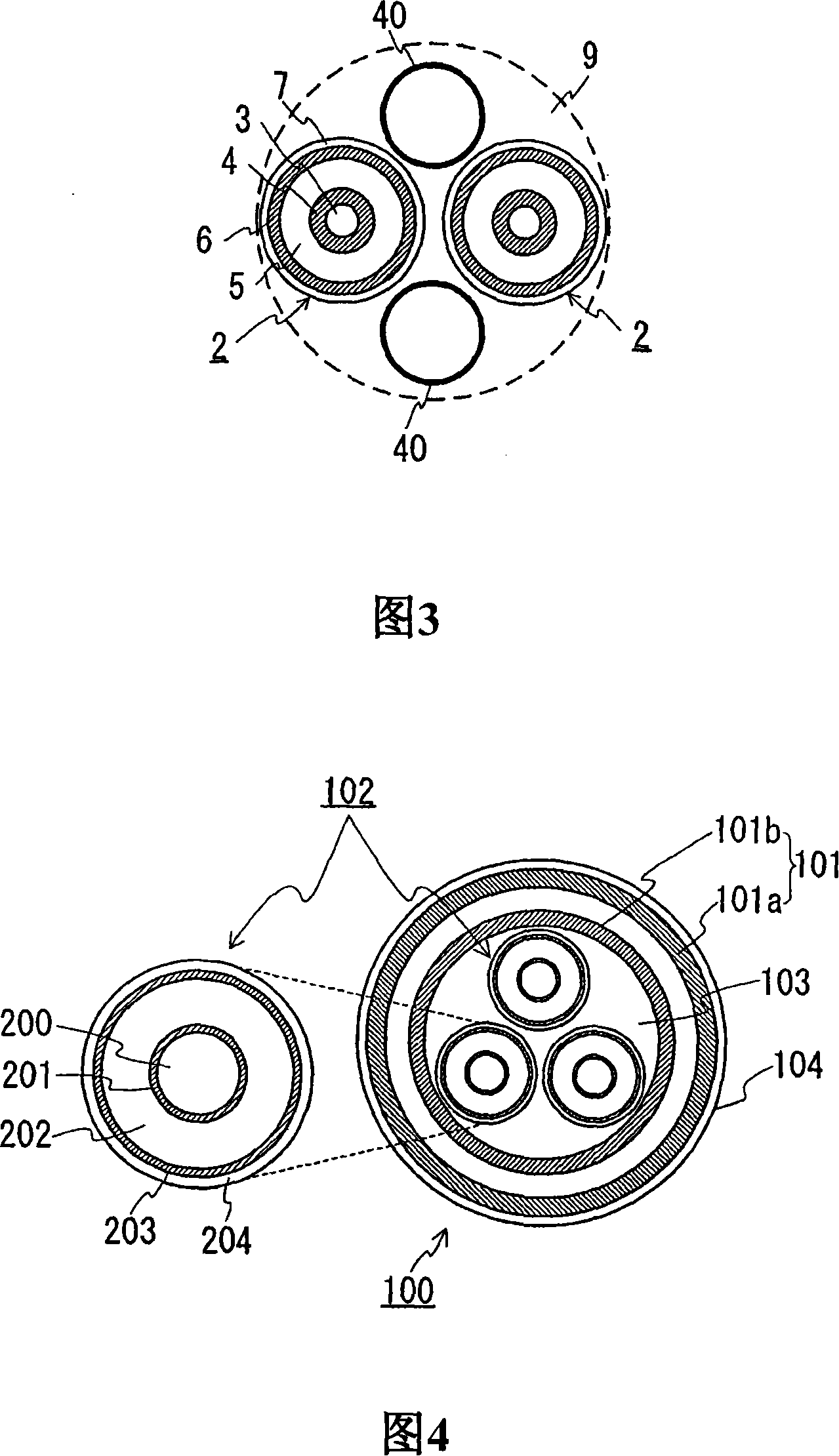
[0080] Next, an explanation is given of a structure provided with both the coolant external passage and the coolant return passage. Fig. 3 shows a schematic cross-sectional view of a superconducting cable of the present invention, which is formed by twisting two cable cores and a coolant circulation tube together. In the above-mentioned Examples 1 and 2, an explanation was given of the structure in which the inner side of the inner pipe of the heat insulating pipe is used as the coolant passage. However, as shown in FIG. 3, the coolant circulation pipe 40 may be provided separately so that the void 9 in the inner pipe can be used as an external passage of the coolant so that the inside of the coolant circulation pipe 40 can be used as a return flow of the coolant. aisle. When the external passage and the return passage of the coolant are provided as described above, the intrusion of heat can be reduced.

[0081] In this example, two coolant circulation pipes 40 are prepared ...


PUM

PropertyMeasurementUnit
diameteraaaaaaaaaa
diameteraaaaaaaaaa
electrical resistivityaaaaaaaaaa

Abstract

A superconducting cable having a smaller outside diameter and a DC power transmission method utilizing this superconducting cable. The superconducting cable (1) comprises two stranded cable cores (2) each having a superconductor layer (4) of a superconducting material and an external superconducting layer (6) and contained in a heat insulating pipe (8). Each cable core (2) consists of a former (3), the superconductor layer (4), an insulating layer (5), the external superconducting layer (6), and a protective layer (7) arranged sequentially from the center. In the case of unipolar transmission, the superconductor layers (4) provided to both cores (2) are fed with an unipolar current and used as a supply line and the external superconducting layers (6) provided to both cores (2) are fed with a return current and used as a return line. In the case of bipolar transmission, the superconductor layer (4) provided to one core (2) is used for positive pole transmission, the superconductor layer (4) provided to the other core (3) is used for negative pole transmission, and the external superconducting layers (6) of both cores (2) are used as a neutral line layer.

Description

technical field [0001] The present invention relates to a superconducting cable formed by twisting together a plurality of cable cores and a DC transmission system including the superconducting cable. In particular, the invention relates to superconducting cables whose diameter can be further reduced. Background technique [0002] As an AC superconducting cable, a known three-core twisted type cable is formed by twisting three cable cores together. Fig. 4 is a cross-sectional view of a three-core twisted type cable for three-phase AC. The superconducting cable 100 has a structure in which three cable cores 102 are twisted together and accommodated in a heat insulating tube 101 . The heat insulation pipe 101 has a double pipe structure composed of an outer pipe 101a and an inner pipe 101b between which a heat insulating material (not shown) is provided. The space between the outer tube 101a and the inner tube 101b is evacuated. On the outer periphery of the heat insulatin...

Claims


Application Information

Patent Timeline
Patent Type & Authority Applications(China)
IPC IPC(8): H01B12/08H01B12/16
CPCY02E40/642H01B12/06Y02E40/60H01B12/08H01B12/16
Inventor 广濑正幸
Owner SUMITOMO ELECTRIC IND LTD
Why Eureka
Try Eureka