
Motor vibration avoidance structure

A vibration isolation and motor technology, applied in the direction of the casing/cover/support, electrical components, electromechanical devices, etc., can solve the problems of shortened system life, electronic system resonance, serious noise, etc.

Inactive Publication Date: 2008-03-19
SUNONWEALTH ELECTRIC MACHINE IND
View PDF0 Cites 3 Cited by
  • Summary
  • Abstract
  • Description
  • Claims
  • Application Information

AI Technical Summary

Problems solved by technology

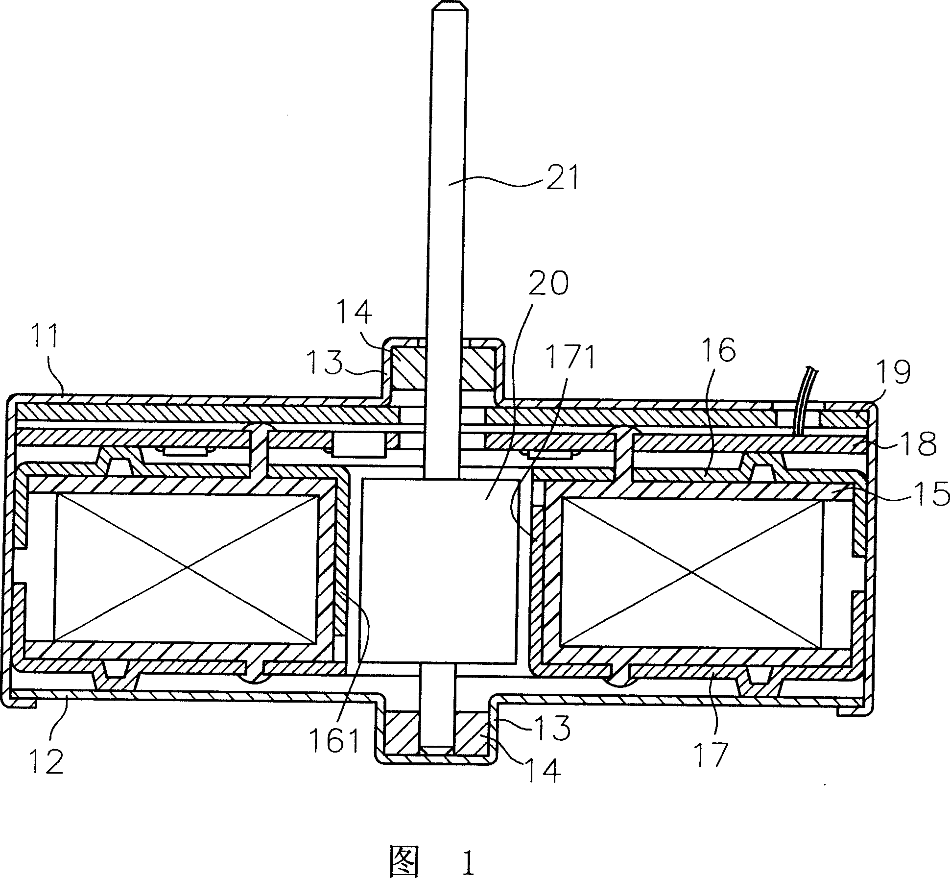
[0005] However, when the above-mentioned motor is actually in operation, because the vibration of the rotor rotation of the motor will be transmitted outward through the rotating shaft and bearings, it will cause serious resonance in the entire motor and even the surrounding electronic system, resulting in the following disadvantages:
[0006] 1. Serious resonance: when the motor is running, the vibration generated by the rotation of the rotor 20 and the friction between the shaft 21 and the bearing 14 will be directly transmitted to the entire motor through the shaft seat 13, thereby affecting the normal function of the surrounding electronic system , causing severe resonance in the electronic system
[0007] 2. The life of the motor and the system is shortened by the resonance effect: the resonance effect not only affects the efficiency of the entire electronic system, but when the system is in a vibrating environment for a long time, it will accelerate the premature fatigue and aging of the contacts of its internal electronic components, shortening the life of the system
[0008] 3. Serious noise: the resonance effect is also accompanied by huge noise, which has a great impact on the overall noise value evaluation of the system

Method used


Image

  • Motor vibration avoidance structure
  • Motor vibration avoidance structure
  • Motor vibration avoidance structure

Examples


Embodiment Construction

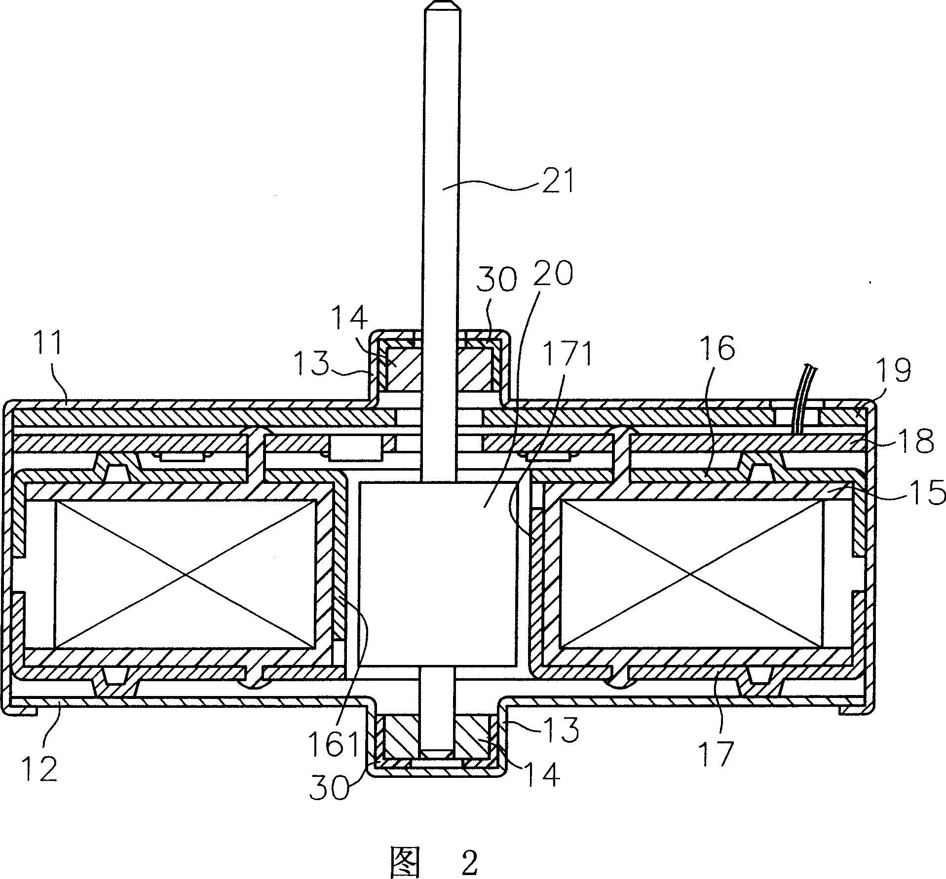
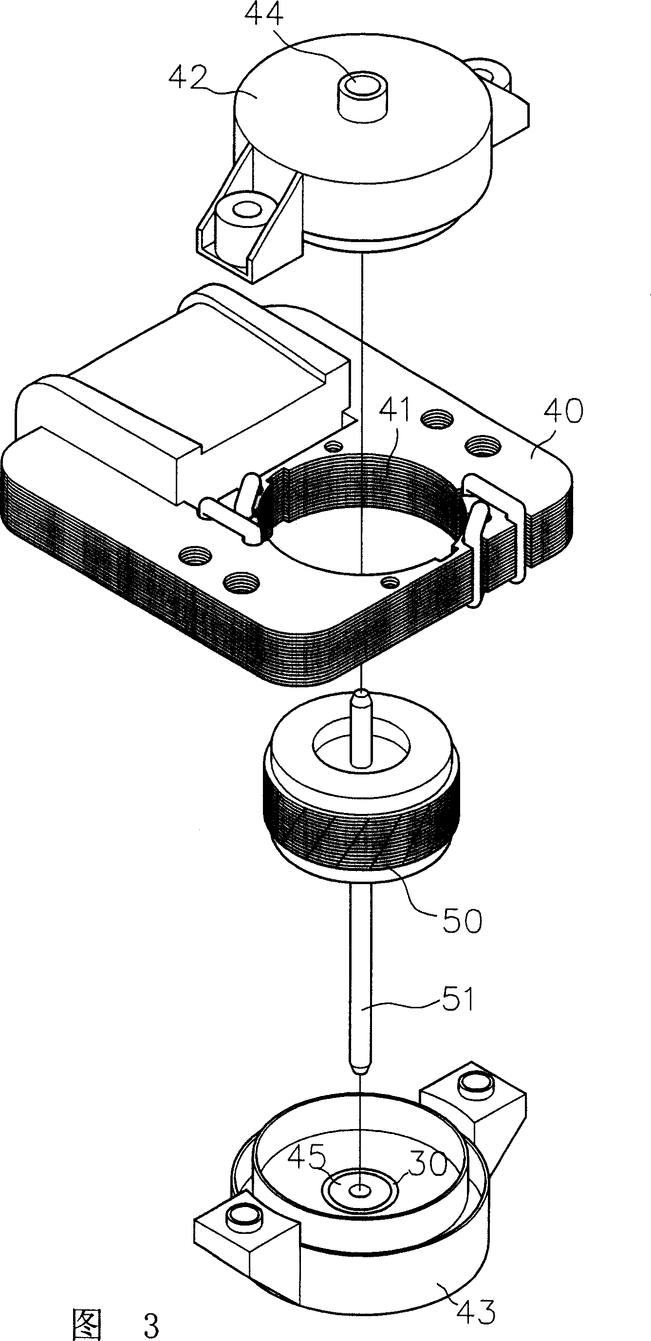
[0021] The present invention relates to a vibration-proof structure for a motor. An anti-vibration component with vibration-absorbing and buffering functions is arranged between the shaft seat and the bearing of the upper and lower housings of the motor, so as to reduce the amount of vibration caused by the rotation of the rotor and the vibration generated by the friction between the rotating shaft and the bearing. The amount will not be transmitted outwards to block the impact of the vibration amount on the system.

[0022] The following is a list of several implementations of the present invention that are actually applied to motors, together with the accompanying drawings, to illustrate the structure, features and advantages of the present invention:

[0023] As shown in Fig. 2, the present invention includes an upper shell 11 and a lower shell 12, wherein both the upper shell 11 and the lower shell 12 are made of magnetically conductive material, and the upper shell 11 and ...


PUM


Abstract

The invention relates to a motor vibration absorption structure, which comprises an upper shell and a lower shell, wherein the upper shell and the lower shell are respectively equipped with a shaft seat, and a bearing is respectively provided in the two shaft seats; a rotor connected with a rotating shaft, which is rotatably articulated between the bearings of the two rotating shafts; and a vibration absorption component respectively is equipped between the shaft seat and the bearing, wherein the vibration absorption component has to be made from elastic material capable of both absorbing and buffering the vibration. The inventive vibration absorption component can absorb, isolate and buffer the vibratory magnitude due to the rotor's rotation and the vibratory magnitude due to friction of the rotating shaft and bearing, so as to avoid the influence of the vibratory magnitude on an electronic system, and sustain the normal efficacy and service life thereof.

Description

technical field [0001] The invention relates to a motor vibration-proof structure, in particular to a motor vibration-proof structure which can block and buffer the vibration of the motor rotor rotation, so as to protect the system and maintain its normal function and service life. Background technique [0002] As shown in Figure 1, it is a motor with axial winding and radial air gap, which includes an upper shell 11 and a lower shell 12 made of magnetically permeable materials, and the upper shell 11 and the lower shell 12 are respectively provided with shaft seats 13. A bearing 14 is arranged in the shaft seat 13 . [0003] The upper and lower shells 11, 12 are provided with axially wound coil holders 15 inside. The coil holders 15 are made of insulating material, and then wound axially with metal wires. The metal wires have ends that can be used as power input, and The coil base 15 has a central hole for the magnetic poles 161, 171 of the upper silicon steel sheet 16 and...

Claims


Application Information

Patent Timeline
IPC IPC(8): H02K5/24H02K5/04
Inventor 洪银树黄世昌
Owner SUNONWEALTH ELECTRIC MACHINE IND
Learn More