Device for a preparatory machine for spinning

A machine controller and equipment technology, applied in spinning machines, drafting equipment, textiles and papermaking, etc., can solve the problems of fiber parallelism damage, incorrect drawing of sliver, damage of fiber sliver, etc., to reduce costs , the effect of simplifying the operation

Active Publication Date: 2008-03-26
RIETER INGOLSTADT SPINNEREIMASCHENBAU AG
View PDF0 Cites 7 Cited by
  • Summary
  • Abstract
  • Description
  • Claims
  • Application Information

AI Technical Summary

Problems solved by technology

[0008] Accumulation of particles on the inner wall of the sliver delivery tube can also cause damage to the fiber sliver to be deposited, especially at high and very high deposition speeds
For example, particle buildup can lead to incorrect drawing of the sliver, or damage to the parallelism of the fibers

Method used


Image

  • Device for a preparatory machine for spinning
  • Device for a preparatory machine for spinning
  • Device for a preparatory machine for spinning

Examples


Embodiment Construction

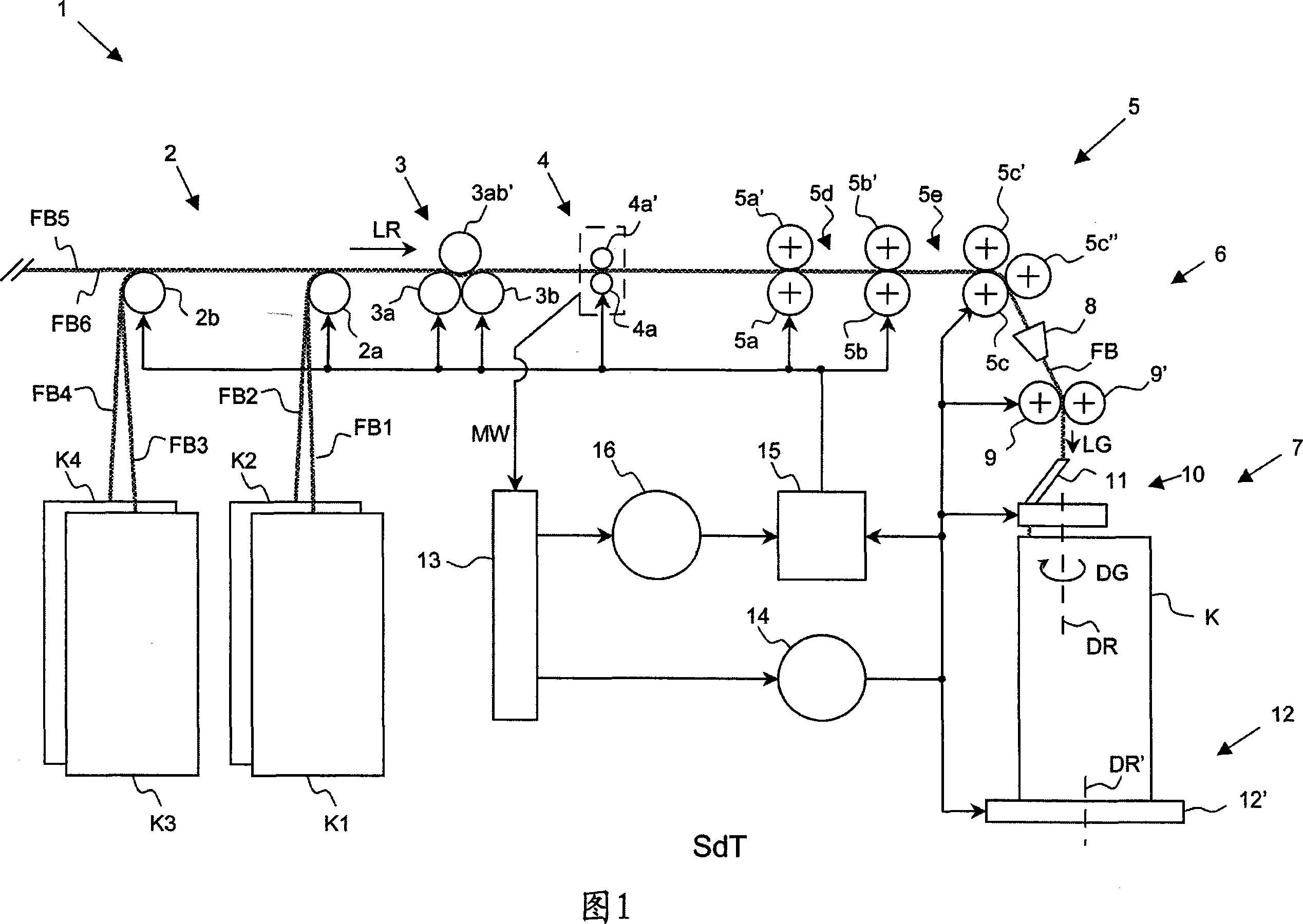
[0043] FIG. 1 shows a schematic side view of a spinning frame 1 as an example of a spinning preparation machine 1 . The fiber slivers FB1 , FB2 , FB3 , FB4 , FB5 and FB6 in front of the spinning frame 1 are conveyed together in the direction of movement LR on the feed table 2 , the inlet roller device 3 , the inlet sensor device 4 and the drawing system 5 . The fiber slivers FB1 , FB2 , FB3 , FB4 , FB5 and FB6 are then combined by the transfer device 6 to form a single compact fiber sliver FB. They are then conveyed at a defined conveying speed LG to the device 7 with which the fiber sliver FB is deposited in the sliver can K.

[0044] The feed table 2, shown schematically only, incorporates a first feed table roller 2a, which is arranged so that the first fiber sliver FB1 in front of the machine can be drawn from the placed sliver tube K1 by the drawing frame 1. The second fiber sliver FB2 can be drawn out from the sliver drum K2 placed in an offset position. A second infee...


PUM


Abstract

Disclosed is an equipment used for a spinning preparation machine (1) especially for a drawing frame (1) or a carding machine (7), it is used for placing fiber carding bar (FB) with assignalble conveying speed (LG) to supply by a conveying device (6) into a carding bar barrel (K), the equipment (7) has a carding bar barrel bracket (12) and a turntable (10) capable of rotating with turntable speed (DG) circling a rotating shaft (DR) and a carding bar transporting tube (11) for transporting fiber carding bar (FB), wherein the carding bar transporting tube (11) has output open (23), wherein a transmitting system (26) is arranged to the turntable (10), it is designed into when the fiber carding bar (FB) is placed into the carding bar barrel (K), according to assignalble collocation (AP,GP), corresponding to the appointed basic speed (GG) generating the turntable speed (DG) declining temporarily, leading the fiber carding bar (FB) longitudinal tension to minish during the speed declining.

Description

technical field [0001] The invention relates to a device according to the preamble of claim 1 for a spinning preparation machine, in particular a drawing frame or a carding machine, for depositing a fiber sliver fed by a transport device at a specifiable transport speed into a sliver can , and to a spinning preparation machine according to the preamble of claim 17. Background technique [0002] It is known in the prior art to deposit a fiber sliver fed by a conveying device at a specifiable conveying speed into a sliver can with the aid of an apparatus of this general type. [0003] The fiber sliver to be deposited passes through a sliver delivery tube associated with a turntable rotating around a vertical axis; the input opening of the sliver delivery tube is concentric with the rotation axis, while the output opening is arranged eccentrically with respect to the rotation axis. The sliver can supporting device is arranged to support the sliver can to be filled, the sliver ...

Claims


Application Information

Patent Timeline
Patent Type & Authority Applications(China)
IPC IPC(8): D01G37/00B65H54/80D01G99/00
CPCD01G15/46D01H5/00B65H54/80B65H2701/31B65H59/385
Inventor 迈克尔·施特罗贝尔
Owner RIETER INGOLSTADT SPINNEREIMASCHENBAU AG
Why Eureka
Try Eureka