Front-and-back opening-closing split self-controllable power air door

A split-type, damper technology, used in mine/tunnel ventilation, mining equipment, earth-moving drilling, etc., can solve the problems of burning out the motor, motor protection, easy leakage failure, etc., and achieve the smooth and smooth process of the damper movement. Smooth running process and the effect of eliminating impact force

Inactive Publication Date: 2008-03-26
陈树林
View PDF0 Cites 17 Cited by
  • Summary
  • Abstract
  • Description
  • Claims
  • Application Information

AI Technical Summary

Problems solved by technology

Therefore, in the prior art, larger dampers are made into a push-pull structure to solve the adverse effect of the wind current on its transmission mechanism, and the power dampers that are powered by power or automatically controlled are rarely used. Using a split structure
In addition, in the prior art, air dampers that use pneumatic or hydraulic transmission all use pressure limiting valves as overload protection for the dampers and their transmission mechanisms, while overcurrent protection is used for overload protection for power dampers that are driven by electric motors. Because these protections are all indirect protection methods, the protection process is slow to reflect, and because the failure rate of the protection device itself is high, the reliability of the protection is poor, especially for the overload protection of the motor. The control capacity of the explosion-proof magnetic starter (that is, the explosion-proof switch) is relatively large, and the power of the motor used on the damper is very small, generally between 2KW and 7.5KW, so these large-capacity switches cannot be used at all. Effectively protect these low-power motors, so motor failures often occur, and if the power of the motor is selected to be large, this means that the dragging capacity of the motor will be increased, even if the motor is implemented on the damper and transmission mechanism. damage, the motor will not be overloaded, so the system cannot be effectively protected
However, the push-pull damper driven by a cylinder or a hydraulic cylinder has a relatively long stroke of the piston rod, and the piston rod is very easy to bend and fail, and is also prone to leakage failures.
And because of the above reasons, the current degree of automation of coal mine dampers is not high. Even if automation is applied, due to its many failures, its normal operation rate is relatively low, and the amount of maintenance is relatively large.

Method used


Image

  • Front-and-back opening-closing split self-controllable power air door
  • Front-and-back opening-closing split self-controllable power air door

Examples


Embodiment Construction

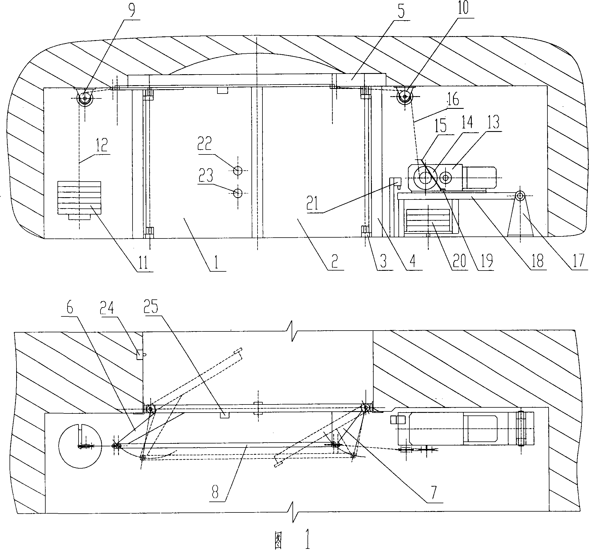
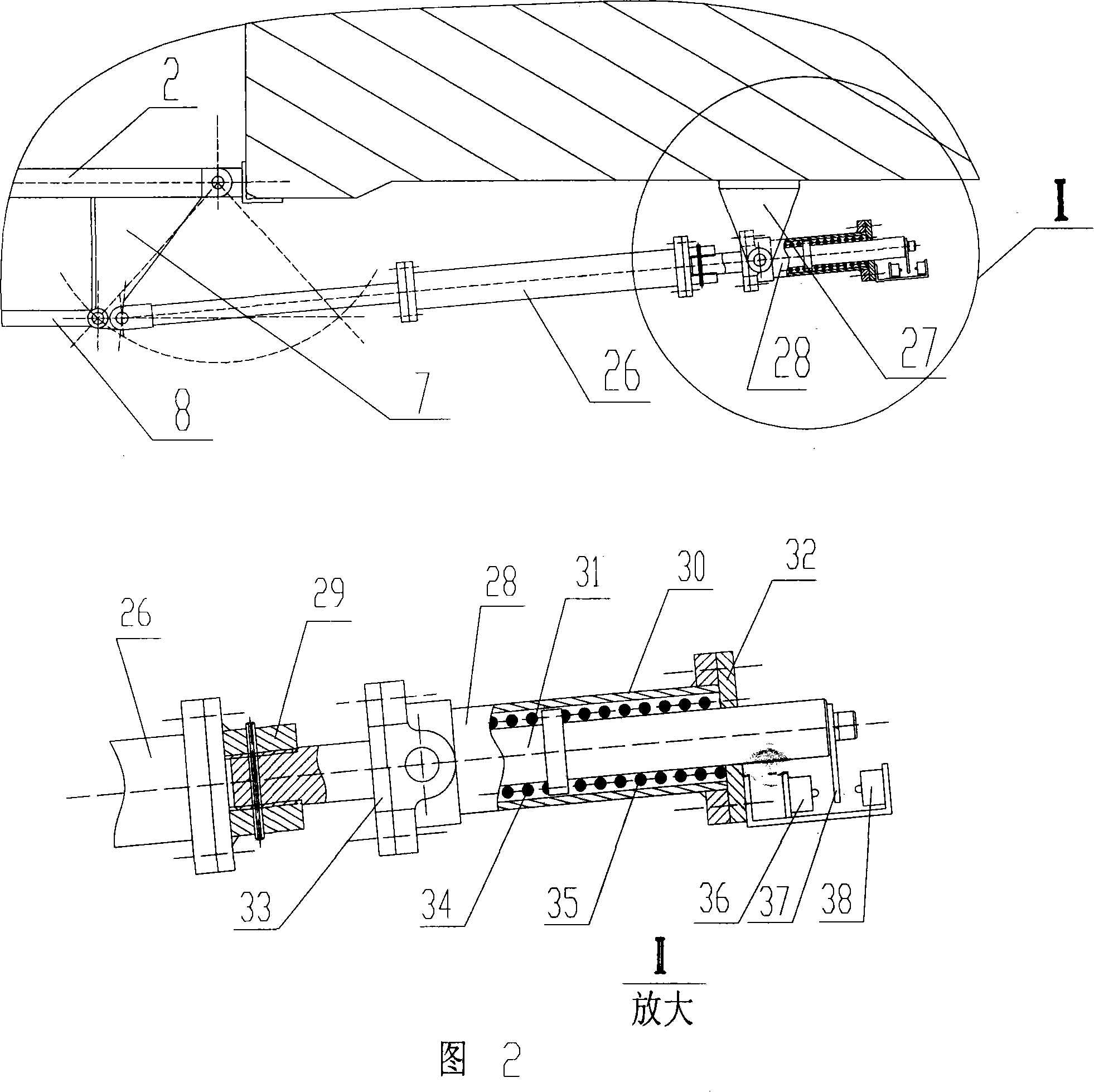
[0019] The front and rear opening and closing split type self-controlling power damper of the present invention is characterized in that the damper consists of a left damper (1), a right damper (2), a hinge (3), a frame (4), a beam (5), a left damper The door crank arm (6), the right door crank arm (7) and the damper power device are composed; the frame (4) is connected with the crossbeam (5) to form the door frame of the damper, which is embedded in the roadway, and the left and right dampers (1) (2) are connected by hinges ( 3) It is hinged with the frame (4), and the left and right door crank arms (6) (7) are respectively fixed to the upper ends of the left and right dampers (1) (2), and the hinged ends are hinged with the connecting rod (8) through the pin shaft, and The hinged end of the right damper or the left damper crank arm (6) (7) is connected with the damper power device. When the power unit dragged one of the curved arms and the damper to rotate, the connecting ro...


PUM


Abstract

The oppositely opened self-controlled powered double air door features two air doors interlinked through crank and link rod and opened or closed oppositely to counteract the acting forces mutually. It has lowered power for opening and closing the air door, no air flow impact, smooth running, no limit in the installation direction of air door and no need of altering the structure in changing the airflow direction. The air door may be driven with a winch or a hydraulic cylinder mechanism. The present invention has simple overall structure, sensitive protection, reliable running and favor to automatic control.

Description

technical field [0001] The invention relates to a damper and a device for automatically opening and closing the damper for ventilation or wind distribution in mines or tunnels. Background technique [0002] For the split damper of the traditional technology, since the opening direction of the damper is only opened in the direction against the wind flow, when the damper is closed or just opened, the force of the wind flow on it is relatively large, especially when the damper is closed. If the corresponding buffer measures are not used, it will also be accompanied by a great impact. Therefore, in the prior art, larger dampers are made into a push-pull structure to solve the adverse effect of the wind current on its transmission mechanism, and the power dampers that are powered by power or automatically controlled are rarely used. It adopts split structure. In addition, in the prior art, air dampers that use pneumatic or hydraulic transmission all use pressure limiting valves...

Claims


Application Information

Patent Timeline
Patent Type & Authority Applications(China)
IPC IPC(8): E21F1/10E21F1/12
Inventor 陈树林
Owner 陈树林
Why Eureka
Try Eureka