Gas-liquid chromatogram separate sampling device and method

A chromatographic separation and sampling device technology, which is applied in the field of preparative gas chromatographic separation

Inactive Publication Date: 2008-03-26
TIANJIN UNIV
View PDF0 Cites 2 Cited by
  • Summary
  • Abstract
  • Description
  • Claims
  • Application Information

AI Technical Summary

Problems solved by technology

Each outlet or inlet has a valve

Method used


Image

  • Gas-liquid chromatogram separate sampling device and method

Examples


Embodiment Construction

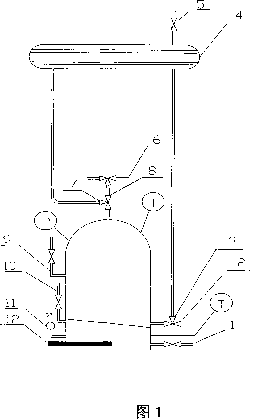
[0013] As shown in the figure, 1 is the heat transfer oil discharge port; 2 is the material discharge port; 3 is the condensate return port; 4 is the condenser; 5 is the vent valve; 6 is the carrier gas inlet; 7 is the steam entering the condenser outlet; 8 9 is the material inlet; 10 is the heat transfer oil inlet; 11-the heat transfer oil vent 12-the heating rod. The valve of the gas-liquid chromatographic separation and sampling device is a ball valve. There are three three-way valves, which are the valves connecting the atmosphere, heating kettle, and condenser; the valves connecting heating kettle, condenser, and chromatographic column; and the valves connecting heating kettle, carrier gas preheating column, and chromatographic column. The rest of the valves are two-way valves.

[0014] This experiment selects n-propanol-water solution as raw material, the feeding amount is 1600ml, and its azeotropic composition under normal pressure is 28.3% (mass fraction of water). T...


PUM


Abstract

The invention relates to the separation sampling device of the gas-liquid chromatogram which includes the tower kettle, the condensator and valve. The kettle top is connected with the condensator through the pipeline, whom the top is connected with the atmospheric valve; the tower kettle is set with the heat-conducting oil outlet, the material outlet, the condensate reflux mouth, the carrier gas inlet, the steam outlet, the material steam outlet, the material adding mouth, the heat-conducting oil adding mouth and heat-conducting oil big air mouth, the kettle bottom has the heating rod; every outlet or inlet is set with the valve. The invention provides a set of the sampling device ahead of gasification. So it can reach the big batch of sampling of the preparative chromatography and has evidence practical value.

Description

technical field [0001] The invention relates to a preparative-level gas chromatography separation technology, in particular to a gas-liquid chromatographic separation and sampling device and method, which can realize relatively large batches of preparative-level chromatographic sampling. Background technique [0002] Preparative gas chromatography is one of the effective methods for separating azeotropes. Preparative gas chromatography has the characteristics of low energy consumption, good separation effect, and environmental protection. Therefore, it has broad application prospects for the separation of a large number of azeotropes in the chemical and pharmaceutical industries. Preparative chromatography is developed on the basis of analytical chromatography. Many of the basic principles are the same, but there are also important differences. Analytical chromatographic systems require fewer injections or trace injections, which is conducive to the formation of symmetrical...

Claims


Application Information

Patent Timeline
Patent Type & Authority Applications(China)
IPC IPC(8): G01N30/16
Inventor 白鹏文青
Owner TIANJIN UNIV
Why Eureka
Try Eureka